Examination
If the camshaft or valve related components are removed, installed or replaced, or if abnormal engine performance occurs over time due to changes in valve clearances, check as follows:
1. Remove the valve cover. See section «Valve lid».
2. Measure valve clearances as follows:
- A. Set the piston of cylinder Na 1 to TDC on the compression stroke.
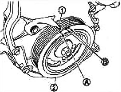
Check crankshaft pulley (2) clockwise and align the TDC mark (colorless risk) (A) with sync pointer (1) on the front cover.
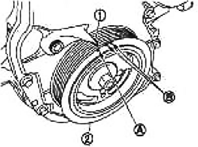
B. White paint mark
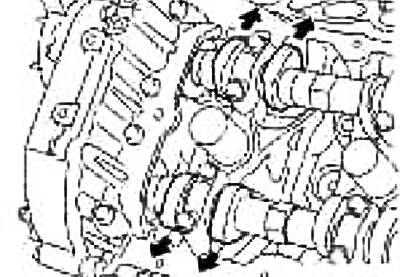
At the same time, check that the lobes on the intake and exhaust camshafts of cylinder #1 are aligned as shown.
Otherwise, turn the crankshaft pulley one more turn (360°) and align the marks as shown in the figure.
- b. Using a feeler gauge, measure the valve clearances between the valve lifters and the camshaft.
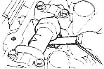
Valve clearances:
Unit: mm
| Valve | Cold engine | Hot engine* |
| Inlet | 0,26-0,34 | 0,304-0,416 |
| Release» | 0,29-0,37 | 0,308-0,432 |
*: Approx 80°C (reference data)
Guided by the figure, use a feeler gauge to measure the valve clearances in the places marked with the mark «X», as indicated in the table below (in the figure, the places are marked with black arrows).
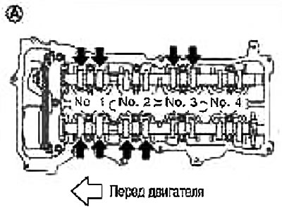
- With. Check crankshaft pulley (2) for one turn (360°) clockwise and align the TDC mark (colorless risk) (A) with sync pointer (1) on the front cover.
Guided by the figure, use a feeler gauge to measure the valve clearances in the places marked with the mark «X», as indicated in the table below (in the figure, the places are marked with black arrows).
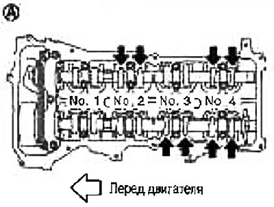
| Cylinder | №1 | №2 | №3 | №4 | |
| Measurement location | Inlet | X | X | ||
| Release | X | X | |||
3. If the measured value is out of specification, adjust.
Adjustment
Note: Adjust according to the selected tappet thickness.
1. Remove the camshaft. See section «Withdrawal».
2. Remove the valve lifters whose clearances differ from the norm.
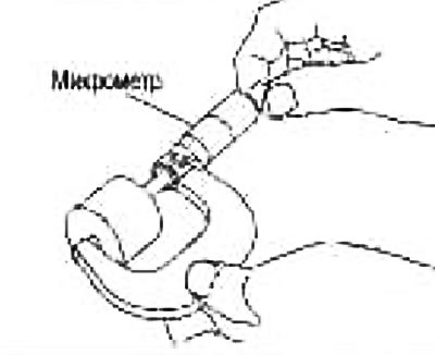
3. Using a micrometer, measure the thickness at the center of the removed valve lifters.
4. Calculate the thickness of the valve lifter using the following formula.
Valve lifter thickness calculation:t=t1+ (C1-C2)
Where:
t — Thickness of replaceable valve stem
t1 — The thickness of the removed valve lifter
C1 - Measured valve clearance
C2 - standard valve clearance
Inlet: 0.30mm
Outlet: 0.33mm
The thickness of the new valve lifter can be found by the marking stamped on the back (inside the cylinder).
Marking «300» means thickness 3.00mm
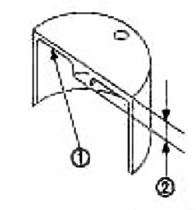
1. Marking
2. Valve lifter thickness
Note: Valve lifters are available in 26 thicknesses ranging from 3.00 to 3.50 mm in 0.02 mm increments (when manufactured at the factory).
5. Install the selected valve lifter.
6. Install the camshaft. See section «Installation».
7. Turn the crankshaft pulley by hand a few turns.
8. Based on the standard values, make sure that the valve clearances on a cold engine are within specifications. See section «Examination».
9. Install all removed components in the reverse order of removal.
10. Warm up the engine and check for unusual noise and vibration.