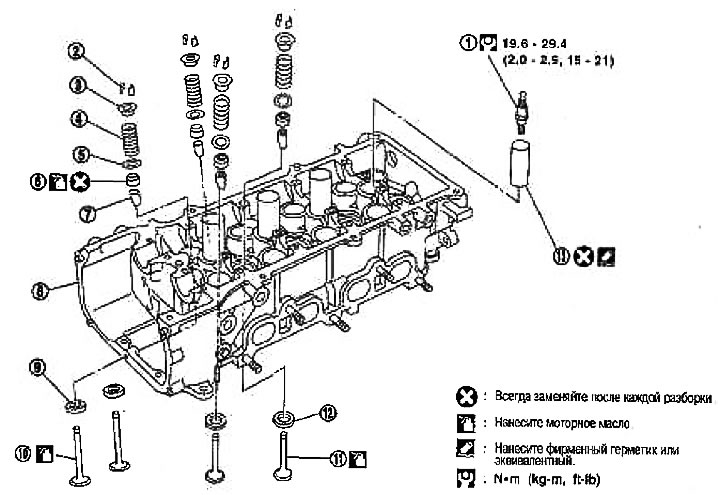
1. spark plug; 2. Crackers; 3. Valve spring plate; 4. Valve spring; 5. Valve spring seat; 6. Valve seal; 7. Valve guide; 8. Cylinder head; 9. Valve seat (inlet); 10. Valve seat (release); 11. Valve (release); 12. Valve (inlet); 13. Spark plug tube
Disassembly
1. Turn out spark plugs by means of a key.
2. Remove the valve lifters.
Mark the valve lifters for reassembly.
3. Take out the crackers.
Compress the valve spring with tool (special tool). Remove the crackers with a finger magnet.
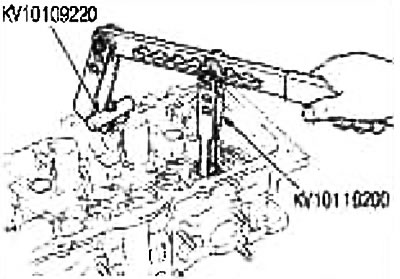
Attention: When performing this operation, do not damage the holes for the valve lifters.
4. Remove the valve spring cup and valve spring.
5. Push the valve stem towards the combustion chamber and remove the valve.
Check valve guide clearance before removal. See section «Valve guide clearance».
Mark the valves for reassembly.
6. Remove the valve gland with a puller (special tool).
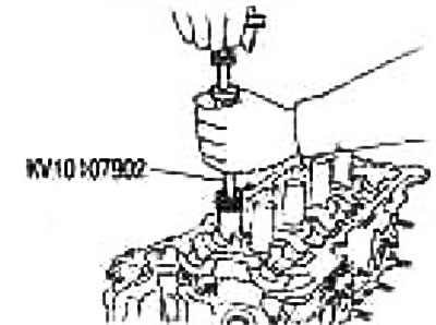
7. Remove the valve spring seat.
8. If valve seat needs to be replaced, see below «Valve seat replacement».
9. If the valve guide needs to be replaced, see below «Valve Guide Replacement».
10. If necessary, remove the spark plug tubes.
Remove the spark plug tubes from the cylinder head with pliers.
Attention: Do not damage the cylinder head. After removal, the spark plug tube is deformed and must be reinstalled. Take it out only when absolutely necessary.
Assembly
1. Install the valve guide. See below «valve guide».
2. Install the valve seat. See below «Valve seat replacement».
3. Press in a new valve seal.
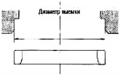
Press the valve seal with a punch (special tool) according to the dimensions shown in the figure.
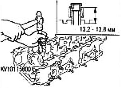
4. Install the valve spring seat.
5. Install the valve.
Note: Install larger diameter valves on the intake side.
6. Install valve spring.
7. Establish a plate of a valvate spring.
8. Install crackers.
Compress the valve spring with tool (special tool). Place the crackers with a finger magnet.
After installing the valve components, lightly tap the tip of the valve stem with a plastic mallet to ensure proper seating.
9. Install the valve lifter.
Install to original position.
10. Install the spark plug tube
Press in the spark plug tube as follows:
- A. Remove the old sealant from the mounting hole in the cylinder head.
- b. Apply sealant to the area on the press-in side of the spark plug tube.
Use branded sealant or equivalent.
- With. Press the spark plug tube with a punch so that its height «H» was as shown in the picture.
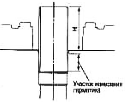
Standard press-in height «H»: 41.0-42.0 mm.
Caution: Do not deform the spark plug tube when pressing. After pressing, remove the sealant that has protruded from the upper surface of the cylinder head.
11. Screw in the spark plug with a wrench.
Check after disassembly
Warping of the cylinder head
1. Wipe off the oil and use a scraper to remove scale, gasket residue, sealant and carbon deposits from the surface of the cylinder head.
Caution: Do not allow gasket residue to enter oil or coolant passages.
2. Check if the bottom surface of the cylinder head is warped by measuring in six directions as shown in the figure.
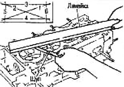
Limit: 0.1mm
If warpage exceeds the limit, replace the cylinder head.
Valve sizes
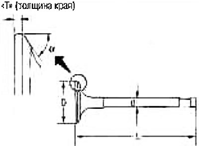
Check the dimensions of all valves.
If the dimensions are out of specification, replace the valve (see pic).
Valve guide clearance.
Perform this check before removing the valve guide.
1. Verify that the valve stem diameter is within specification.
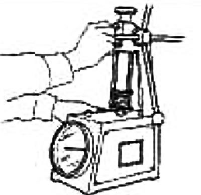
2. Push the valve about 15 mm towards the combustion chamber, move the valve towards the indicator (1) and measure the amount of movement.
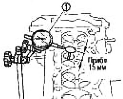
3. Valve guide clearance is 1/2 gauge reading.
| Standard | Inlet | 0.020-0.053 mm |
| Release | 0.040-0.073 mm |
Valve guide replacement.
If the valve guide is removed, replace it with an oversized guide (by 0.2 mm).
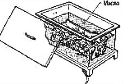
1. Remove the valve guide by heating the cylinder head to 110-130°C by immersing it in hot oil.
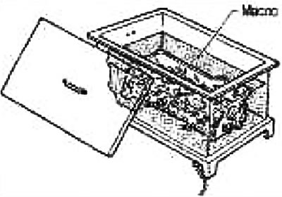
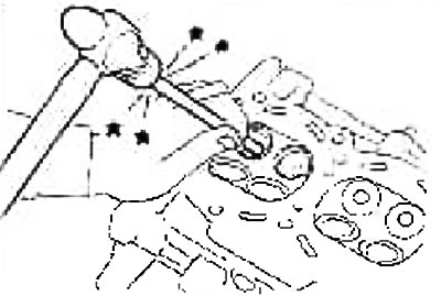
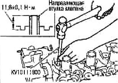
2. Press out the valve guide using a press [with a force of 20 kN (2 tons)] or knock out with a hammer and a suitable drift.
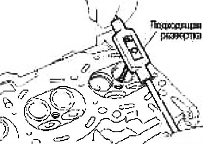
3. Ream the valve guide hole in the cylinder head with a reamer.
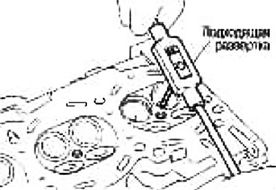
Valve guide hole diameter (repair size). Inlet and outlet: 9.685-9.696 mm.
4. Heat the cylinder head to 110-130°C by immersing it in hot oil.
5. Press in the valve guide from the camshaft side using the dimensions shown in the figure.
Caution: The cylinder head is hot. Wear protective clothing to avoid burns while working.
6. Use a reamer to finish the surface of the valve guide.
| Standard | Release | 5.500-5.518 mm |
Valve seat contact pattern
Perform this check, making sure that the dimensions of the valve guides and the valves themselves are within specifications.
Apply red lead (or lead white) on the contact surface of the valve seat and check the fit of the valve to the seat.
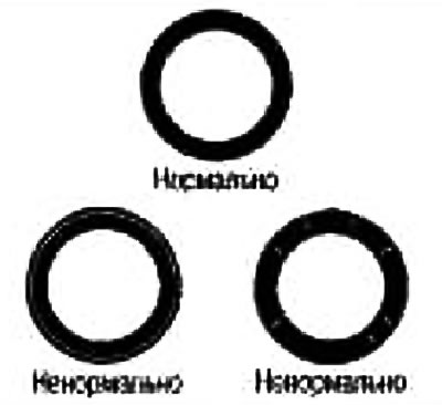
Make sure that the red lead imprint shows up around the circumference without breaks.
Otherwise, achieve the required degree of valve fit by regrinding and check again. If the contact surface is still unsatisfactory even after rechecking, replace the valve seat.
Valve seat replacement
If the valve seat is removed, replace it with an oversized valve seat (by 0.5 mm).
1. Drill out the old seat until it breaks. Drilling must not continue deeper than the bottom of the seat recess in the cylinder head. For this purpose, put a drilling depth gauge on the drill.
2. Ream out the notch in the cylinder head for the oversize valve seat.
| Increased size (by 0.5 mm) | Inlet | 29.000-29.016 mm |
| Release | 24.000-24.016 mm |
Ream in concentric circles towards the center of the valve guide. This will ensure proper seating of the valve seat.
3. Heat the cylinder head to 110-130°C by immersing it in hot oil.
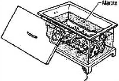
4. Cool the valve seats well with dry ice. Press the valve seats into the cylinder head.
Caution: Do not touch chilled saddles with bare hands. The cylinder head is hot. Wear protective clothing to avoid burns while working.
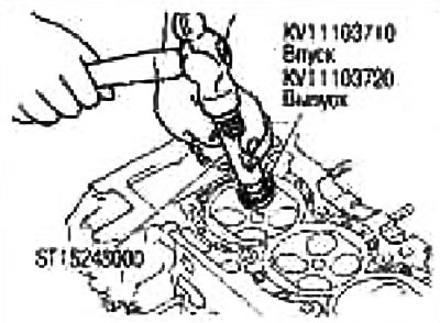
5. Finish the seat to the required dimensions by milling or grinding with a suitable special tool.
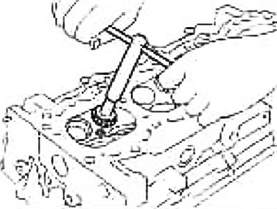
Attention: When processing a surface with a milling cutter, grasp the handle with both hands. Then press the cutter against the contact surface around the entire circumference and mill in single passes. If the tool is pressed unevenly or with a break, the valve seat may take a stepped shape.
Carry out processing until the dimensions indicated in the figure are obtained.
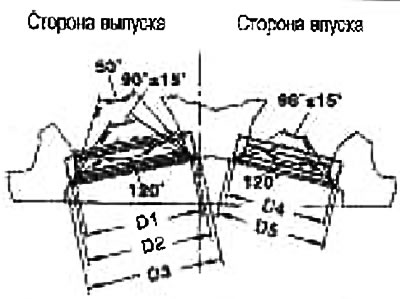
Standard:
- Diameter D1: 25.4mm
- Diameter D2: 27.0-27.2mm
- Diameter D3: 28.7-28.9mm
- Diameter D4: 22.0-22.2mm
- Diameter 05: 23.7-23.9mm
6. Lappe the valve with grinding paste.
7. Recheck valve seat.
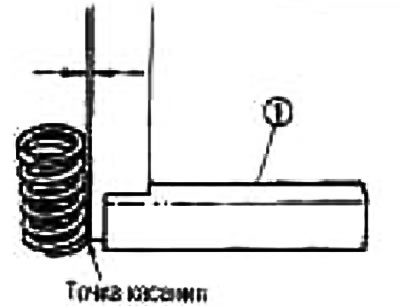
Valve spring straightness
Attach a square (1) to the valve spring and rotate the spring. Measure the maximum gap between the top of the spring and the square (1). Limit: 1.6 mm.
If the clearance exceeds the limit, replace the valve spring.
Valve Spring Dimensions and Compression Force
Check valve spring compression at standard spring height.
Standard:
- Length unloaded: 53.3 mm
- Height after installation: 32.82 mm
- Load after installation: 149-165 N (15.2-16.8 kg)
- Valve Open Height: 24.73mm
- Load with open valve: 228-250 N (23.3-25.5 kg)
If the specified values are out of specification, replace the valve spring.
