Mitsubishi starter assembly
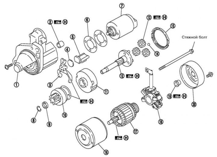
1 - Front cover; 2 - Bushing; 3 - Drive lever; 4 - Plate; 5 - Sealing element; 6 - Adjusting plate; 7 - Traction relay; 8 - Lock washer; 9 - restrictive ring; 10 - Overrunning clutch assembly; 11 - Internal transmission; 12 - Planetary gear shaft; 13 - Planetary gear; 14 - Ball; 15 - Clip; 16 - Housing; 17 - Anchor; 18 - Brush holder assembly; 19 - Rear bearing; 20 - Back cover
Bosch starter assembly
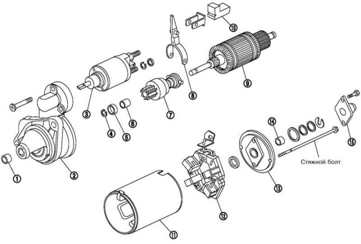
1 - Bushing; 2 - Front cover; 3 - Traction relay; 4 - Lock washer; 5 - Restrictive ring; 6 - Bushing; 7 - Assembling the overrunning clutch; 8 - Drive lever; 9 - Anchor; 10 - Sealing element; 11 - Housing; 12 - Brush holder assembly; 13 - Back cover; 14 - Bushing; 15 - Lid
1. Before checking traction relay disconnect the negative wire from the battery and the wire from the terminal «M» starter.
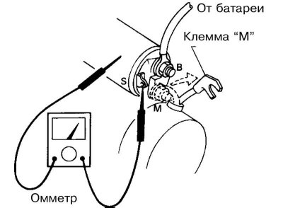
2. Make sure there is continuity between the terminal «S» and ground of the traction relay, as well as between the terminal «S» and terminal «M». Otherwise replace the traction relay.
3. Check the condition of the teeth freewheel gears, as well as the teeth of the reduction gear (Mitsubishi starter). The freewheel gear should rotate smoothly in one direction and lock up if it is attempted to rotate in the opposite direction. Replace the freewheel assembly if necessary.
4. Check the wear of the brushes, the smoothness of their movement in the holder, measure the length of the brushes and compare it with the requirements Specifications. Replace brushes if necessary.
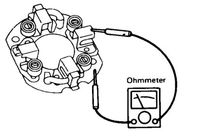
4. Make sure that between the positive side brush holder and its foundation (negative side) no conductivity.
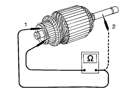
5. Check anchor: there must be continuity between the two segments of the commutator, but there must be no conductivity between each segment and the shaft.
6. Measure the diameter of the manifold and compare it with the requirements Specifications.
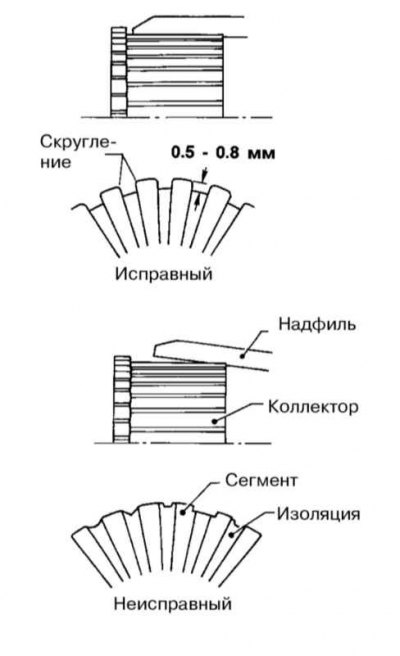
7. Check the depth of the collector grooves - it should not be less than 0.2 mm. If necessary, make grooves up to 0.5÷0.8 mm.
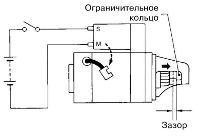
8. With the freewheel pulled out, press the clutch to take up the slack and measure the gap between the front edge of the freewheel and its stop ring. Compare the result with the requirements Specifications and, if necessary, adjust the gap by selecting the adjusting plates.