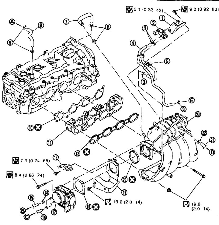
Intake manifold 1. Bracket; 2. EVAP charcoal filter purge solenoid valve; 3. Clamp; 4. EVAP hose; 5. EVAP hose assembly; 6. Clamp; 7 PCV hose; 8. Fresh air hose; 9. Clamp; 10. Gasket; 11. Intake manifold adapter; 12. Gasket; 13. Bracket; 14. Clamp; 15. Water hose; 16. Water hose; 17. Electric throttle drive; 18. Gasket; 19. Intake manifold support; 20. Gasket; 21. Vacuum hose; 22. Clamp; 23. Intake manifold; A. To the air duct; B. To the heater pipe; C. To the outlet pipe; D. To the brake booster; E. To vacuum tube/charcoal filter).
Removal and installation
Removal
1. Relieve fuel pressure. See chapter "Engine management system".
2. Remove the hood grille cover. See chapter "Interior and exterior equipment".
3. Remove the air cleaner housing, mass air flow sensor and air duct and resonator assembly. See above.
4. Remove the electric throttle valve as follows:
- A. Disconnect the connector.
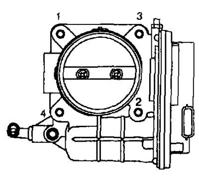
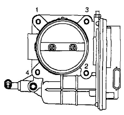
- b. Loosen the mounting bolts in the reverse order shown in the figure and remove the electric throttle actuator and gasket.
Attention:
- Handle the electric drive with care and avoid shock.
- Don't take it apart.
Note. If only the intake manifold is being removed, move the electric throttle valve without disconnecting the water hose.
5. Disconnect the electrical wiring, vacuum hose and PCV hose from the intake manifold and move them to the side.
6. Remove the intake manifold support.
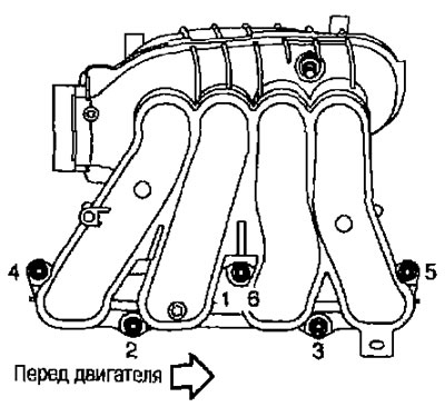
7. Loosen the mounting bolts and nuts in the reverse order shown in the illustration and remove the intake manifold and gasket.
Attention. To prevent foreign particles from entering, seal the opening in the motor.
Note. Ignore #6 when weakening.
8. Disconnect the intermediate wiring from the fuel injectors. See below.
9. Remove the fuel pipe and fuel injector assemblies from the intake manifold adapter. See below.
10. If necessary, remove the EVAP charcoal filter purge solenoid valve from the intake manifold.
Installation
Installation is carried out in the reverse order of removal, taking into account the following.
Intake manifold
- If the studs were turned out, screw them in and tighten them to the required torque.
9.4 Nm (0.96 kg-m)
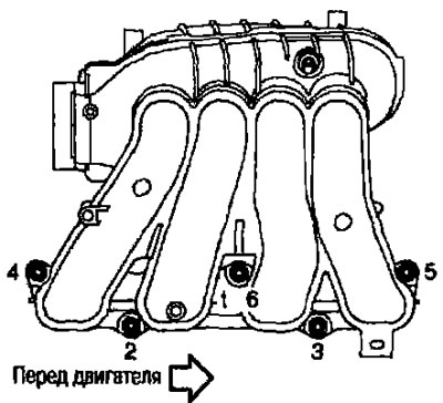
- Tighten the bolts in the order indicated by the numbers in the figure below.
Note. #6 means tighten bolt #1 twice.
Electric throttle valve
- Tighten the bolts evenly crosswise in several passes in the order indicated by the numbers in the figure.
- When disconnecting the connector from the electric throttle valve, «Closed throttle teaching». See chapter "Engine management system".
- When replacing the electric throttle actuator, carry out «Air supply training at idle speed.» and «Closed throttle teaching». See chapter "Engine management system".
Check after removal
Surface warping
- Using a ruler (A) and feeler gauge (IN) Check whether the contact surface on both sides of the exhaust manifold adapter is warped.
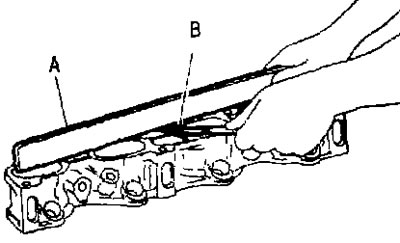
Limit: See section below «Technical data and specifications».
- If warpage exceeds the limit, replace the exhaust manifold and/or exhaust manifold adapter.