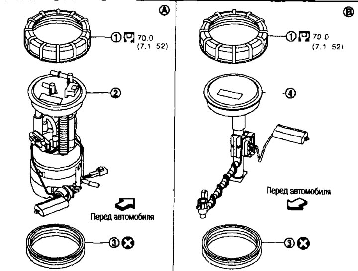
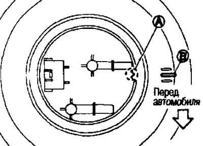
Fuel level sensor, fuel filter and fuel pump assembly. 1. Retaining ring; 2. Fuel level sensor, fuel filter and fuel pump assembly; 3. O-ring; 4. Intermediate fuel level sensor; A. On the right side; B. On the left side.
Attention. Do not remove or disassemble components unless instructed to do so in the illustration.
Removal and installation
Removal
1. Check the fuel level. If the indicator shows a level greater than in the figure (full or almost full tank), drain the fuel from the tank and bring the gauge readings to the level shown in the figure or less.
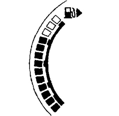
Note. The fuel is drained in order to avoid spilling fuel when removing the fuel level sensor, fuel filter and fuel pump assembly. the fuel level is above the sensor mounting surface.
- As a guide, the fuel level drops to the level shown in the figure or lower after draining approximately 15 liters of fuel from the tank.
- If the fuel pump does not work, do the following:
A. Insert a hose with a diameter of less than 20 mm into the filler pipe through the hole and drain the fuel from the filler pipe.
b. Disconnect the filler hose from the filler pipe. See below.
With. Insert the hose into the fuel tank through the filler hose and drain the fuel from the fuel tank.
2. Relieve fuel pressure in the fuel lines. See chapter «Engine management system».
3. Open the fuel filler door.
4. Remove the filler cap and relieve the pressure inside the fuel tank.
5. Remove the rear seat cushion See chapter «Interior and exterior equipment».
6. Remove the cover from the inspection hatch.
- Remove the cover by turning the clips 90°clockwise using a screwdriver.
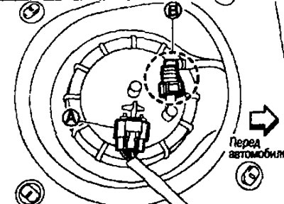
7. Disconnect the connector (A) and quickly removable fitting (IN).
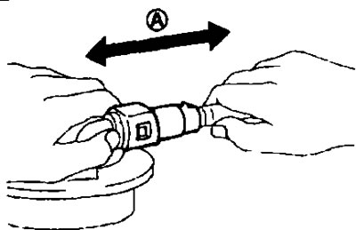
Disconnect the quick release fitting as follows:
- Grasp the fitting on both sides, press in the latches and remove it.
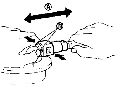
A. Pull; B. Press in the latches.
- If the fittings are stuck to the main fuel level sensor tube, move them back and forth several times until they come free. Then disconnect them by pulling them in different directions.
Attention. Quick release fitting (1) can be detached when the latches (F) completely recessed. Do not twist it more than necessary.
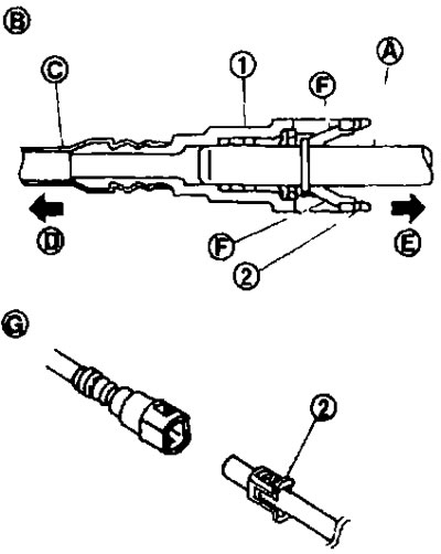
B. Connection (cross section); D. To the fuel line under the bottom; E. To the fuel tank; G. Disconnection.
- Do not remove the quick release fitting using any tools.
- Protect the plastic tube (WITH) from exposure to heat. Especially when carrying out welding work near the tube.
- Do not allow acid-containing liquids, such as battery fluid, etc., to come into contact with the plastic tube.
- Do not bend or twist the plastic tube when connecting or disconnecting.
- Do not remove the lock (2) with hard tube (or equivalent) (A), except when replacing a plastic tube or clamp.
- When replacing plastic tube or hard tube (or equivalent) also replace the retainer. Retainer color: Brown.
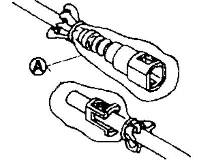
- To keep the connection area clean and to prevent damage and foreign particles, plug the openings of the disconnected pipes with plugs or cover them completely with plastic bags (A).
- Unscrew the locking ring using a wrench (suitable special tools).
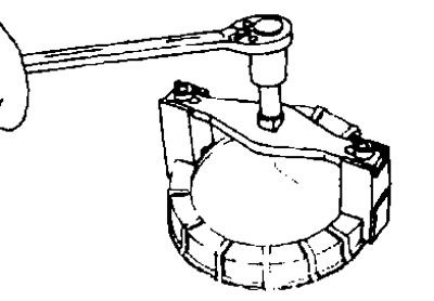
Note. To facilitate subsequent installation, apply alignment marks to the retaining ring, fuel pump assembly, and fuel tank.
9. Lift the fuel level sensor, fuel filter and fuel pump assembly (1) and disconnect the fuel pipe and connector.
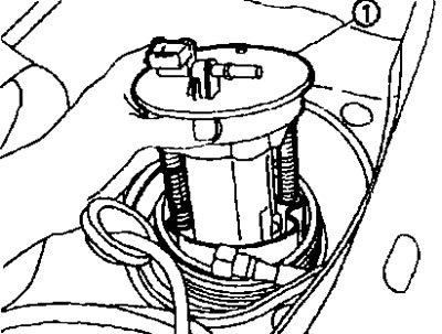
Attention:
- Do not bend the float lever when removing it.
- Avoid getting any remaining fuel inside. Remove at a right angle, supporting it with a cloth.
- Do not hit or drop components.
10. Lift the intermediate fuel level sensor.
Attention:
- Do not disconnect the fuel pipe from the intermediate fuel level sensor assembly.
- Do not bend the float arm when removing it.
- Avoid getting any remaining fuel inside. Remove at a right angle, supporting it with a cloth.
- Do not hit or drop components.
Installation
Installation is carried out in the reverse order of removal, taking into account the following:
Fuel level sensor, fuel filter and fuel pump assembly and intermediate fuel level sensor assembly.
1. Place the O-ring on the fuel tank without twisting it.
2. Install the fuel level sensor with the marks aligned (A) on the sensor and (IN) on the fuel tank, as shown. in Fig.
Note:
- The illustration shows the fuel level sensor, fuel filter and fuel pump assembly from the fuel tank side.
- The alignment mark for the intermediate fuel level sensor assembly is located on the front of the fuel tank.
Quick release fitting
Connect the fuel pipe quick release fitting as follows:
1. Make sure there is no damage or foreign matter deposits in and around the fuel pipe and quick connector.
2. Center the fitting with the tube, then insert the fitting at a right angle into the tube until it clicks.
3. After connecting, make sure the connection is secure by following these steps:
- Perform a visual check to ensure that both latches are engaged in the fitting.
- Pull (A) for the tube and fitting and check the reliability of the connection.
Inspection point cover
Before installing the cap, make sure there are no fuel leaks in the installation area. See below.
1. Install the inspection hatch cover with the front mark (arrow) towards the front of the car.
2. Secure the clamps by turning them counterclockwise.
Check after installation
Check for fuel leaks as follows:
1. Turn the ignition key to position «ON» (without starting the engine). After creating pressure in the fuel lines, check for fuel leaks at the joints.
2. Start the engine. Let the engine run at idle speed. and check for fuel leaks at the joints of the fuel lines.