Attention. The direction of rotation indicated in the text refers to rotation as viewed from the front of the engine.
Removal
1. Remove the following components:
- intake manifold; see above,
- valve cover; see above,
- front cover and timing chain related components; see above.
Note. There is no need to remove components associated with the balance block.
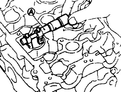
2. Remove the camshaft angle sensor (PHASE) from the camshaft bracket.
Attention:
- Handle the sensor carefully and do not hit it.
- Do not disassemble the sensor.
- Do not leave the sensor in places where it may be exposed to magnetism.
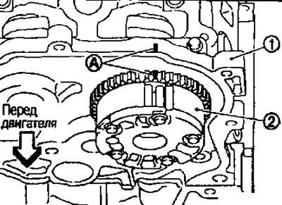
3. Apply an alignment mark (A) to the intake camshaft sprocket (2) and camshaft bracket (1), as shown in the picture.
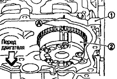
Note. This operation is intended to prevent the intake camshaft guide from entering an unintended hole when installing the intake camshaft sprocket.
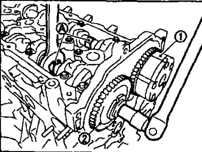
4. Remove the intake camshaft sprockets (1) and graduations (2) valves
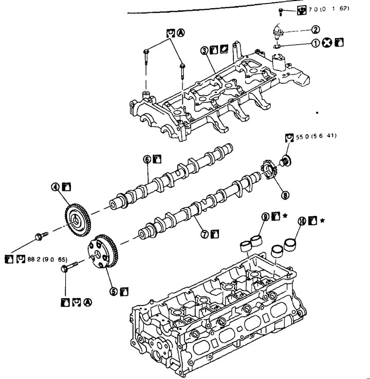
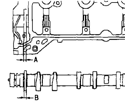
Camshafts 1. O-ring; 2. Camshaft angle sensor (PHASE); 3. Camshaft bracket; 4. Camshaft sprocket (release); 5. Camshaft sprocket (inlet); 6. Camshaft (release); 7. Camshaft (inlet); 8. Signal disk; 9. Valve lifters (release); 10. Valve lifters (inlet); A. See below.
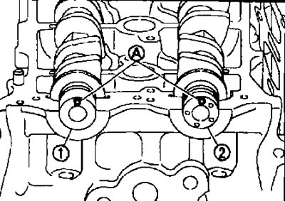
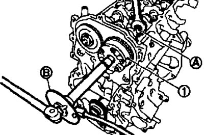
- Secure the camshaft with the hexagon (A) so that it does not turn. Loosen the camshaft sprocket mounting bolts and remove the sprockets.
Attention:
- After removing the timing chain, do not rotate the crankshaft or camshafts individually, otherwise the valves will hit the piston crowns.
- Do not loosen the mounting bolts by securing components other than the camshaft hex or by tensioning the timing belt.
5. Remove the camshaft bracket as follows:
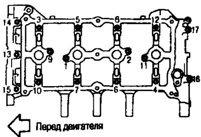
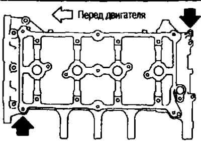
A. Loosen the mounting bolts in the reverse order shown. in the picture.
b. Pry up the cover in the places indicated. arrows (
Attention:
- Do not damage the contact surfaces.
- When shipped from the factory, a more durable sealant is applied than previously used sealants. Therefore, you should not try to separate the cover in places not intended for this purpose.
6. Remove the camshafts.
7. Remove the valve tappets.
- Mark the locations and place the components in order without mixing them.
8. If necessary, remove the signal disc from the intake camshaft.
Installation
1. Install the valve lifters.
- Install them in the same places they were in before removal.
2. Install the camshafts.
- Clean the camshaft journals from foreign particles.
- Intake and exhaust camshafts can be identified by the shape of the front and rear ends or by distinctive markings (A) And (IN).
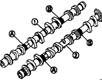
1. Exhaust camshaft.
2. Intake camshaft.
| Color coding | A | IN |
| Exhaust camshaft | — | White |
| Intake camshaft | White | — |
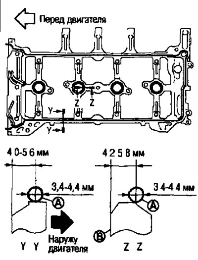
- Install the camshafts so that the guide protrusions (A) on the front ends stood as shown in the figure.
1. Exhaust camshaft.
2. Intake camshaft.
Note. Although the camshafts are not installed in the position shown in the illustration for installing the cam lobes, it is generally acceptable for the camshafts to be installed in the same direction as in the illustration.
3. Install the camshaft bracket as follows:
A. Completely remove any foreign matter from the back of the camshaft bracket and from the mounting surface in the cylinder head.
b. Apply sealant (A) onto the camshaft bracket as shown in the figure.
B. The inner walls of the hole for the candle.
- Use branded sealant or equivalent.
With. Tighten the camshaft bracket mounting bolts in several passes in the order indicated by the numbers in the illustration.
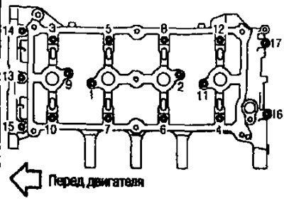
There are two types of mounting bolts:
- M6 (thread length: 57.5mm) Nos. 13, 14 and 15.
- M6 (Thread length. 35 mm), except as stated above.
I. Tighten the mounting bolts in the order indicated by the numbers in the figure.
II. Tighten the mounting bolts in the order indicated by the numbers in the illustration.
III. Tighten the mounting bolts in the order indicated by the numbers in the illustration.
Attention. After tightening the camshaft bracket mounting bolts, remove any excess sealant that has protruded from the contact surface of the cylinder head.
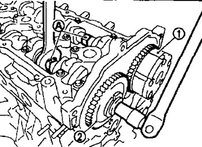
4. Install the intake camshaft sprocket onto the intake camshaft as follows:
A. When removing the intake camshaft sprocket (2) follow the alignment mark (A), applied with paint in step 3. Align the guide protrusion and the hole for it and connect them.
1. Camshaft bracket.
b. Tighten the following bolts. way:
- When tightening the mounting bolts, secure the intake camshaft at the hexagonal part.
1. Tighten the intake camshaft sprocket mounting bolts.
2. Tighten the bolt 67 clockwise (angle tightening).
Attention. Check the tightening angle with a protractor wrench (special tool KV10112100) (IN) or a protractor. Avoid assessing by eye without the use of tools.
1. Intake camshaft sprocket.
A. Hexagonal part of the intake camshaft.
5. Install the sprocket on the exhaust camshaft at (2).
- When tightening the mounting bolts, secure the intake camshaft at the hexagonal part (A).
1. Intake camshaft sprocket.
6. Install the timing chain and related components. See above.
7. Check and adjust valve clearances. See above.
8. Install the remaining components in the reverse order of removal.
Check after removal
Camshaft runout
1. Install the camshaft on two prisms with journals No. 2 and No. 5.
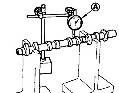
Attention: Do not install the camshaft on the prisms with journal No. 1 (from the camshaft sprocket side), because its diameter is different from the other four.
2. Attach the sensitive indicator head (A) vertically on neck No. 3.
3. Rotate the camshaft manually in one direction and measure the runout with an indicator (maximum indicator reading).
Standard and limit. See section below «Technical data and specifications».
4. If the runout exceeds the limit value, replace the camshaft.
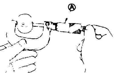
Camshaft lobe height
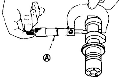
1. Measure the camshaft cam height with a micrometer (A).

Standard and Limit: See section below «Technical data and specifications».
2. If wear exceeds the limit value, replace the camshaft.
Oil gap in camshaft journals
Camshaft journal outer diameter. Measure the outer diameter of the camshaft journal with a micrometer (A).
Standard: See section below «Technical data and specifications».
Camshaft bracket inner diameter
- Tighten the camshaft bracket bolts to the required torque. Refer to higher.
- Measure the inner diameter of the camshaft bracket with a bore gauge (A).
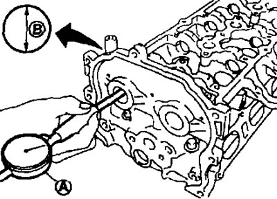
B. Location for measuring the internal diameter.
Standard: See section below «Technical data and specifications».
Oil gap on camshaft journals (Oil gap in journals) = (camshaft bracket inner diameter) - (camshaft journal outer diameter)
Standard and limit. See section below «Technical data and specifications».
- If the clearance exceeds the limit, replace either the camshaft or cylinder head, or both.
Note. The camshaft bracket is manufactured in one piece with the cylinder head. Replace the cylinder head assembly.
Camshaft end play
1. Install the camshaft into the cylinder head. See above.
2. Set the indicator (A) in the axial direction with the sensitive head to the front end of the camshaft. Measure the end play by moving the camshaft forward/backward (in axial direction).
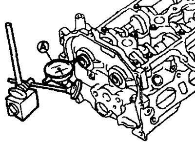
Standard and Limit: See section below «Technical data and specifications».
- If the end play is abnormal, measure the dimensions of the following components:
Size «A» grooves for journal No. 1 in the cylinder head.
Standard: 4,000-4,030 mm.
Size "IN" camshaft flange.
Standard 3.877-3.925 mm.
- Compare the measurements with the standard values indicated above and replace the camshaft and/or cylinder head.
Camshaft sprocket runout
1. Install the camshaft on two prisms with journals No. 2 and No. 5.
Attention. Do not install the camshaft on the prisms with journal No. 1 (from the sprocket side of the camshaft), because its diameter is different from the other four.
2. Measure the runout of the camshaft sprocket with an indicator (A) (maximum indicator reading).
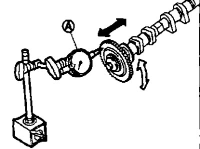
Limit: See section below «Technical data and specifications».
- If the runout exceeds the limit value, replace the camshaft sprocket.
Valve pusher
- Check the valve tappet surface for wear or chips.
- If any defects are found, replace the valve tappet. See section below «Technical data and specifications».
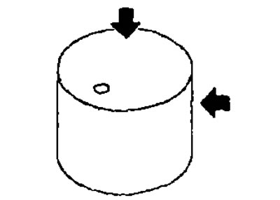
Valve tappet clearance
- Clan pusher outer diameter.
- Measure the outer diameter of the valve tappet with a micrometer (A).
Standard: See section below «Technical data and specifications».
Valve tappet hole diameter
- Measure the diameter of the valve tappet hole in the cylinder head using a bore gauge (A).
Standard. See section below «Technical data and specifications».
Valve tappet clearance (Valve tappet clearance) (valve tappet hole diameter) - (valve tappet outer diameter).
Standard: See section below «Technical data and specifications».
- If the value obtained is not normal for the inner and outer diameters, replace either the valve lifter or the cylinder head, or both.
Check after installation
Checking the lubrication groove on the intake camshaft sprocket.
Attention. To avoid burns from splashing engine oil, perform the inspection when the engine is cold.
1. Check the engine oil level.
See chapter "Engine lubrication and cooling system".
2. Perform the following procedure to ensure that the engine does not start accidentally during testing.
- Relieve fuel pressure. See chapter "Engine management system".
- Remove the intake manifold. See above.
- Disconnect the connectors from the ignition coils and injectors.
3. Remove the intake valve timing control solenoid valve. See above.
4. Clean the installation area of the intake valve timing control solenoid valve and insert a clean, oil-free rag into the lubrication hole (A) in the cylinder head.
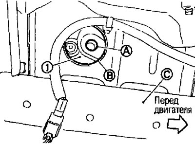
1. Front cover; B. Inspection hatch; C. Beam on the right side.
5. Install the right engine mount insulator (after removing the solenoid valve of the intake valve timing control mechanism and blocking the lubrication hole with a rag).
6. Crank the engine and check if engine oil flows out of the oil hole (installation hole of the solenoid valve of the intake valve timing control mechanism) in the cylinder head.
- Check the engine oil by assessing the amount absorbed into a rag inserted into the oil hole.
Attention:
- Do not put your fingers into the oil hole on the side of the inspection hatch in the beam on the right side of the vehicle.
- Do not touch rotating components (drive belt, tension pulleys and crankshaft pulley, etc.).
- Do not crank the engine without installing the right engine mount insulator.
- To prevent oil from splashing onto a person and causing burns, as well as dirt from getting into the oil, use a napkin.
- Use a cloth to protect engine and vehicle components from oil.
- Do not allow engine oil to come into contact with rubber parts such as the drive belt, engine mount insulators, etc. Immediately wipe up any spilled engine oil.
7. If engine oil does not flow out of the intake valve timing solenoid valve lubrication hole in the cylinder head, perform the following check.
Remove the oil filter (solenoid valve of the intake valve timing control mechanism) and clean it. See above.
- Clean the lubrication groove between the coarse filter and the solenoid valve of the intake valve timing control mechanism. See chapter "Engine lubrication and cooling system".
8. Remove the components between the intake camshaft timing control valve and the intake camshaft sprocket and check for clogged lubrication grooves.
- If necessary, clean the lubrication groove. See chapter "Engine lubrication and cooling system".
9. After checking, install the removed components in the reverse order of removal.