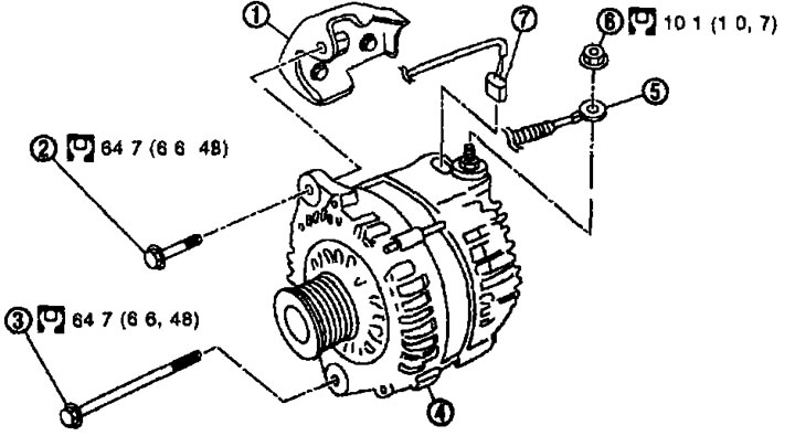
Withdrawal. 1. Generator bracket; 2. Upper generator mounting bolt; 3. Lower generator mounting bolt; 4. Generator; 5. Terminal wiring «B»; 6. Terminal nut «IN»; 7. Generator connector.

Disassembly. Type: LR1110-713C. 1. Stator; 2. Rear bearing; 3. Rotor; 4. Clip; 5. Front bearing; 6. Front cover; 7. Pulley; 8. Fan guide; 9. Labyrinth seal; 10. Voltage regulator assembly; 11. Diode assembly; 12. Back cover; 13. Terminal assembly; 14. Terminal nut «B».
Removal and installation
Removal
1. Disconnect the cable from the negative terminal of the battery.
2. Remove the drive belt. See chapter «Mechanical part of the engine».
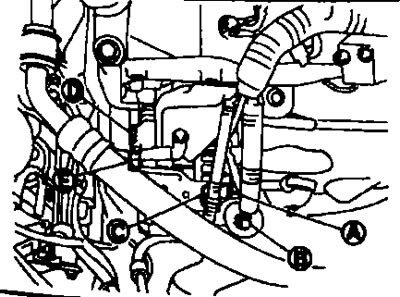
3. Disconnect the connector (A) from the generator.
4. Unscrew the terminal nut «IN» (IN) and disconnect the terminal wiring «IN».
5. Remove the wiring clamp (WITH) with bracket.
6. Unscrew the top mounting bolt (D) generator
7. Unscrew the lower mounting bolt (E) generator
8. Remove the generator from the car towards the top.
Installation
Installation is carried out in the reverse order of removal, taking into account the following:
- Install the generator and check the belt tension. See chapter «Mechanical part of the engine».
Attention. Tighten the terminal nut «IN» with caution.
Disassembly and assembly
Disassembly
Back cover
Note. The back cover may be difficult to remove because The outer ring of the rear bearing is fixed with a ring. To make it easier to remove the back cover, heat only the bearing housing section to approximately 30°C using a 200W soldering iron.

Attention. Do not use a fan heater, otherwise the diode assembly may be damaged.
Front cover
1. Secure the rotor in a vice.

Attention:
- But damage the rotor
- When securing the rotor in a vice, lay copper strips or a thick rag.
2. Using a suitable tool, remove the cover from the pulley.
3.Using generator pulley adapter (special tool) remove the generator pulley.

Assembly
Rear bearing
Attention:
- Once the rear bearing is removed, do not reuse it. Replace with a new one.
- Do not lubricate the rear bearing outer race.
Installing the back cover
1. Install the brush assembly, diode assembly, regulator assembly and stator assembly.

2. Lift the brushes with your fingers and place them on the rotor.
Note. Do not damage the sliding surface of the slip rings.

Examination
Check after disassembly
Rotor check
1. Check resistance.

Resistance. See paragraph below. «Technical data and specifications».
- If the measured value is not normal, replace the rotor.
2. Insulation check.
- If there is continuity, replace the rotor.
3. Check whether the slip rings are worn.
Minimum outer diameter of the slip ring. See paragraph below. «Technical data and specifications».
- If the measured value is not normal, replace the rotor.
Checking the brushes
1. Check whether the brushes rotate freely.
- If they rotate with jamming, check the brush holder and clean it.
2. Check whether the brushes are worn out.

- If wear has reached the limit line, replace the brush.
Stator check
1. Conductivity check.

- If there is no continuity, replace the stator.
2. Checking conductivity to ground.

- If there is continuity, replace the stator.