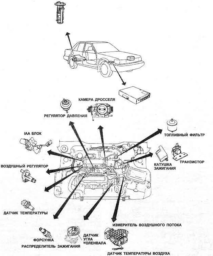
Pic. 3.53. Location of parts for the 2.0 liter fuel injection engine management system

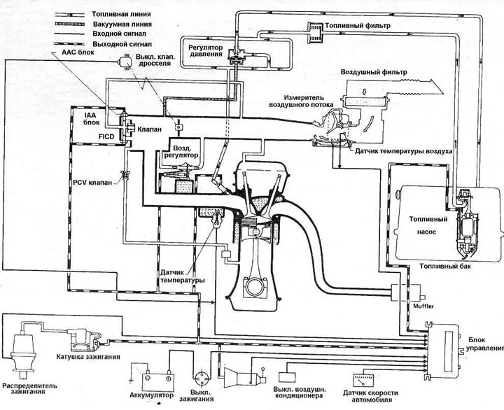
Pic. 3.54. Engine management system - 2.0 liter fuel injection models
The fuel system begins with the fuel tank, which houses the electric fuel pump. It is protected by a mesh filter on the inlet side and a full flow filter on the outlet side. When the ignition is turned on and the starter operates, the pump pumps fuel into the fuel line. Fuel pressure is controlled by a vacuum regulator. The injectors are controlled by windings and are opened and closed by electrical impulses from the ECCS unit; the desired opening moment is determined by the information that the unit receives from the ignition distributor angle sensor. The injector coil retracts the needle valve and allows a certain amount of fuel to pass from the fuel line through the small filter into each injector, to the nozzle; all four injectors turn on simultaneously, twice during each engine cycle.
The induction system takes cool air and passes it through the air filter element into the air flow meter. There the temperature of the incoming air and the required volume are determined. The force of the incoming air deflects the sensor flap, which converts this movement into voltage by a potentiometer; information from these two sensors goes to the ECCS block. The sensor flap is supported by a spring. To adjust the air/fuel mixture at idle, there is a bypass in the air flow meter that is adjusted by a meter screw. From the air flow meter, air flows through the throttle chamber to the intake manifold. The throttle valve switch is mounted outside the throttle chamber and provides the ECCS unit with throttle valve position information. It has two pairs of contacts, one for idle and one for wide open throttle. The amount of air in idle mode is regulated by the IM unit installed on the intake manifold, and controls the idle speed using signals from the ECCS unit, adjusting the amount of air that bypasses the throttle valve. By turning on the ECCS unit only when the throttle valve is closed and the vehicle speed is less than 5 km/h, the IAA unit pei-supplies air according to the signals from the control unit, which are determined from information pre-programmed into the memory. The GAA unit has an idle speed adjustment screw, a vacuum control valve, an LAS valve and (only on Executive models) FICD valve.
The heart of the electronic system is the ECCS unit, it compares information regarding the volume and temperature of incoming air (air flow meter), engine speed (ignition system), throttle valve position (throttle valve switch), and engine temperature (water temperature sensor); it also uses vehicle speed data (speed sensor), whether the air conditioning system is turned on (if installed). The control unit sends signals to the air regulator, AAC valve and fuel pump, to the power transistor and to the fuel injectors. The system is fail-safe, uses multiple programmed injection pulse durations in the event of an airflow meter failure, and assumes set water temperature values in the event of a temperature sensor failure.