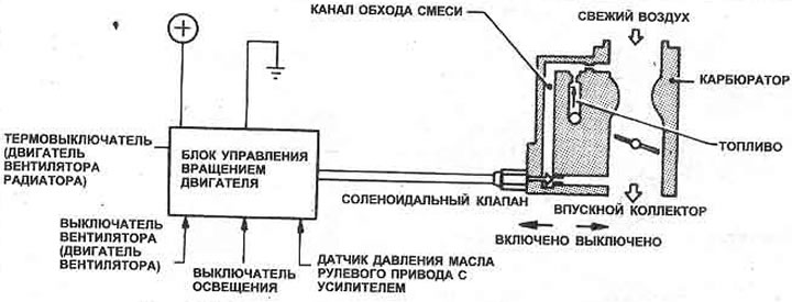
2. The system is activated by the power steering pressure sensor, heater fan switch, electric cooling fan thermal switch and light switch.
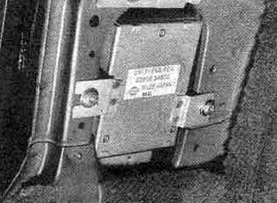
3. The system is controlled by the rotation control unit, which is located on the left side of the driver behind the instrument panel (photo).

Pic. 3.33. Idle control system

19.3. Engine rotation control unit location
4. When one of the switches is triggered, the control unit retracts the valve driven by the winding, which opens the mixture bypass channel.
5. If the idle speed does not increase when the switches are activated, check them as described in the appropriate Section of this manual.
6. To test the idle speed solenoid valve, disconnect the carburetor wiring harness and connect 12 volt battery power to the valve leads. You should be able to hear the valve operate. If faulty, replace it.
7. If a fault is suspected in the control unit, it can only be checked by replacing it with a known-good unit (Section 12).