Adjusting the idle speed
2. Place the vehicle on a flat surface, apply the handbrake, block the wheels, and engage neutral (manual transmission) or position "N" (automatic transmission).
3. The engine must be warmed up to normal operating temperature with the valve clearances adjusted and the ignition timing set. On models without a tachometer, connect an external tachometer to the engine according to the manufacturer's instructions.
4. Start the engine and let it idle for two minutes.
5. Accelerate the engine to 2000-3000 rpm two or three times, putting it in idle mode.
6. Check that all electrical components are turned off and disconnect the electric cooling fan.
7. Measure and compare the idle speed with the data in Specifications. If necessary, adjust the idle speed screw (photo). Connect the electric cooling fan motor.
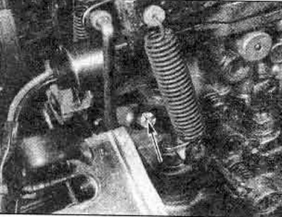
17.7. Idle speed adjustment screw - 1.6 and 1.8 liter models
Adjusting the idle mixture
8. The idle mixture adjustment screw can be turned with a special screwdriver (Nissan number KV10108300). There are various versions of this screwdriver available (photo). Also, a CO meter would be useful (exhaust gas analyzer) and a tachometer where necessary.
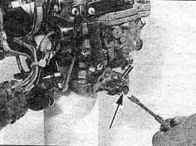
17.8. Special screwdriver for turning the idle mixture adjustment screw
9. The idle mixture is preset at the factory and no further adjustment is required. Adjustment will be required due to changes in engine characteristics (carbon deposits, wear of parts, etc.), or after rebuilding the carburetor.
10. Warm up the engine to normal operating temperature. Disconnect the electric cooling fan motor.
11. Check the CO level. If adjustment is required, turn the idle mixture adjustment screw until the correct setting is achieved.
12. If there is no CO meter, follow the procedure described below. To work, you will need an accurate tachometer.
13. Stop the engine and tighten the mixture adjustment screw until it stops (do not overtighten it, you may damage the tip of the screw), then unscrew it exactly two turns. Start the engine.
14. Remove excess fuel from the intake manifold by accelerating the engine to 2000-3000 rpm two to three times, then idling.
15. Set idle speed to 730 rpm (manual transmission) or 830 rpm (automatic transmission), using the idle speed adjusting screw.
16. Slowly turn the mixture adjustment screw slightly, first in one direction, then in the other, until you find the position where the engine has maximum speed. If the increase in frequency is significant, set the idle speed adjusting screw again to 730 (or 830) rpm
17. If adjustments take more than three minutes, remove excess fuel from the manifold as described in step 14 above.
18. When setting the idle mixture adjustment screw, the engine runs at the fastest speed 730 (or 830) rpm, reduce the idle speed to the standard value by slowly tightening the idle mixture adjustment screw.
19. Stop the engine, disconnect the measuring equipment, connect the electric cooling fan motor.
20. The fuel level can be easily checked by placing the car on a level surface and with the engine running at idle speed.
21. The gasoline level in the float chamber should be at the mark (kah) on glass or frame (see fig. 3.17 and photo).
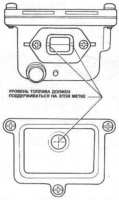
Pic. 3.17. Fuel level marks in the carburetor
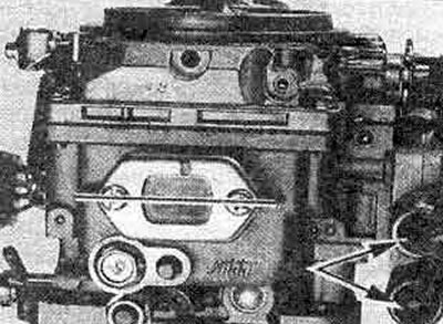
17.21. Note fuel level marks - also idle air control valves and BCDD (marked with arrows)
22. If adjustment is necessary, remove the carburetor.
23. On 1.6 and 1.8 liter models, remove the damper chamber. On 2.0 liter models, remove the float chamber cover and look through the window.
24. Invert the choke chamber or carburetor so that it is completely horizontal.
25. Raise the float, then slowly lower it until it touches the tip of the float adjuster shut-off needle valve and measure the gap between the top of the float and the top of the chamber (gap 'Y', Fig. 3.18).
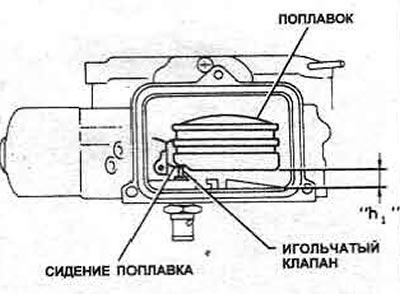
Pic. 3.18. Float height measurement - valve closed
26. To adjust, carefully bend the float holder (Pic. 3.19 and 3.21).
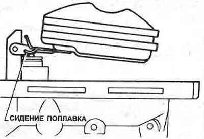
Pic. 3.19. Float seat location - 1.6 and 1.8 liter models
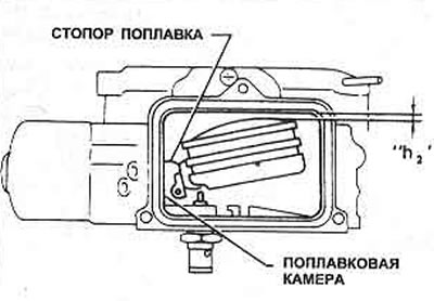
Pic. 3.21. Float height measurement - valve fully open
27. Then raise the float (carburetor still upside down) until the float stopper touches the chamber wall and measure the gap between the base of the float and the base of the float chamber (gap 'h2', Fig. 3.21). On 1.6 and 1.8 liter models, it is necessary to measure the depth of the chamber from the center of the body surface (or gaskets) and the height of the float base above the chamber surface (or gaskets). Subtract the second measurement from the first to get the clearance. Don't forget to include the gasket thickness.
28. If adjustment is required, carefully bend the float holder until the correct setting is achieved.
29. Reassemble the carburetor using a new float chamber cover gasket and install it on the vehicle.
30. Check the fuel level.
Checking high idle speed
31. Warm up the engine to normal operating temperature.
32. Connect the tachometer (If you want to) according to the manufacturer's instructions.
33. Locate the adjusting screw on the high idle speed cam (Pic. 3.22). Start the engine, check (fast idle mode) the received frequency.
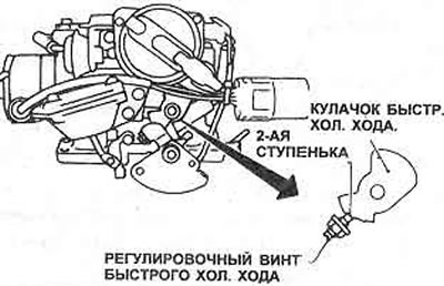
Pic. 3.22 Setting the fast cold draft. stroke when measuring high idle speed
34. If the measured frequency differs from the specified one, remove the carburetor (Chapter 20) and damper chamber (Chapter 21).
35. Using the fast idle adjustment screw on the idle cam, set the size "A" (Pic. 3.23) between the primary throttle valve and the diffuser wall within the specified tolerances. To adjust, loosen the locknut and turn the adjusting screw. After adjustment, tighten the locknut.
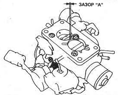
Pic. 3.23. Gap between the primary throttle valve and the carburetor diffuser wall
36. Assemble the carburetor and install it on the car, repeat the test.
Dashpot adjustment
37. First, warm up the engine to normal operating temperature and check that the valve clearances, ignition timing, accelerator cable adjustment, idle speed and mixture, and fuel level are set correctly.
38. Connect the tachometer (If you want to), according to the manufacturer's instructions.
39. With the engine idling, slowly open the throttle pulley/lever by hand until the lever contacts the dashpot plunger. Note the engine speed in this position.
40. If adjustment is required (see Specifications), remove the carburetor (Chapter 20) and remove the damper chamber (Chapter 21).
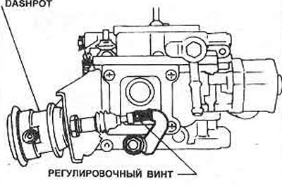
41. Using a suitable size drill, check gap 'A' (Pic. 3.23) between the primary throttle valve and the diffuser wall and compare with the data in the Specifications, then turn the throttle lever adjusting screw (photo), until it touches the tip of the dashpot plunger (pic. 3.24).
Pic. 3.24. Dashpot and Throttle Lever Adjustment Screw - 2.0 Liter Model
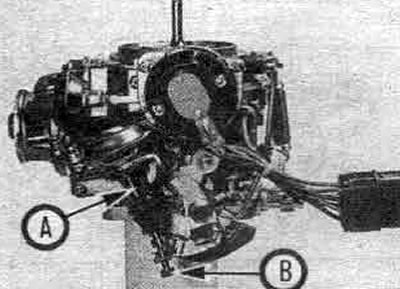
17.41. Dashpot 'A', throttle lever adjustment screw 'B' - 1.6 and 1.8 liter models
42. Assemble the carburetor, install it on the car (Chapters 20 and 21), then check again (paragraphs 37-39 above).
Automatic choke control
43. Remove the air filter cover.
44. Check that the air damper is completely closed, and also check that it moves smoothly and easily throughout its entire range (pic. 3.25).
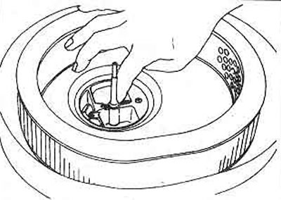
45 Remove the air filter housing. check that the notches on the bimetal chamber and the carburetor body are aligned (Pic. 3.26). Always align these marks during assembly.
Pic. 3.25. Checking the Auto Choke Valve
Pic. 3.26. Carburetor alignment marks and bimetal coating
46. Check the electrical wiring of the automatic choke heater, start the engine, warm it up to normal operating temperature. The air damper should move smoothly, fully opening (photo).
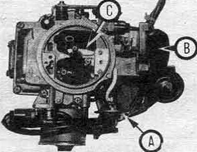
17.46. Vacuum Diaphragm 'A', Auto Choke Heater 'B', Choke 'C'
47. If the choke is not working properly, check the battery voltage at the heater terminal with the engine running. If not, check the warning light/auto choke relay (Section 12 and rice 3.27) and electrical wiring until you find the damage.
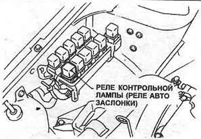
Pic. 3.27. Warning lamp/auto choke relay location
48. If there is battery voltage, check for an open circuit between the heater clamp and the carburetor body (Pic. 3.28). If the circuit is open, then the spring of the bimetallic heating device is broken, in which case the unit must be replaced.
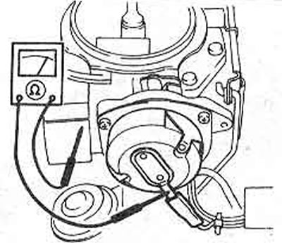
Pic. 3.28. Checking the condition of the automatic choke heater
Vacuum interrupt adjustment
Note: This test requires a vacuum pump. If there is no pump, have your dealer check it.
49. Check the closure of the air damper as described in paragraphs 43 and 44 above, then remove the air filter housing (Chapter 5).
50. Disconnect the rubber tube, connect the vacuum to the vacuum interruption diaphragm (Pic. 3.29).
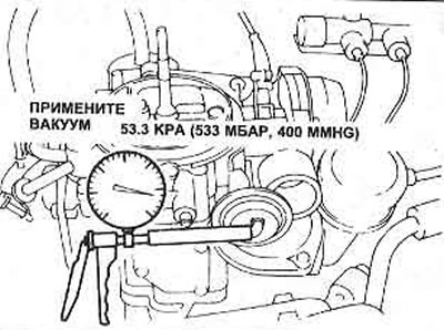
Pic. 3.29. Creating a vacuum
51. Using a screwdriver, push the binding rod in the direction shown (closing the air damper) and measure the gap "R1". If it is out of tolerance, adjust by bending the tongue.
52. Guided by Fig. 3.31, use a screwdriver to push the binding rod towards the diaphragm until it touches, then measure the gap "R2". If he is out of tolerance. repeat checking and adjusting the gap "R1".
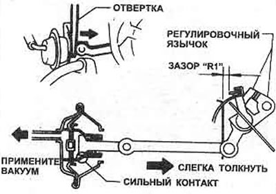
Pic. 3.30. Checking the gap R1
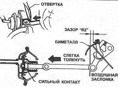
Pic. 3.31. Checking the gap R2
53. Turn off the vacuum, connect the tube, install the air filter.
Action of the accelerator pump
54. Remove the air filter cover.
55. Open the throttle lever fully and check that the pump injector is delivering fuel to the primary port.
56. If not, check the connection between the accelerator pump and the piston (photo).
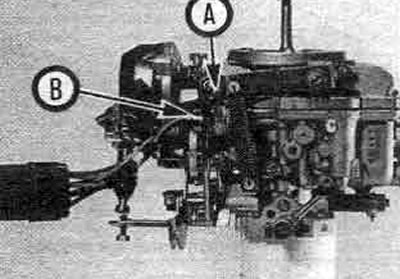
17.56. Accelerator pump thrust 'A', cut-off valve 'B'
Fuel shut-off valve
57. With the engine idling, disconnect the carburetor wiring (photo); the engine should stop immediately. Replace the valve coil if it does not work.
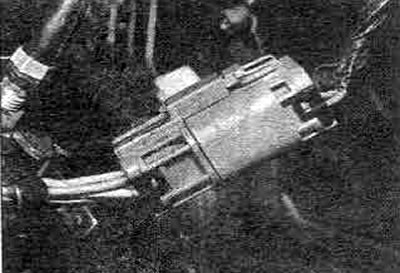
17.57. Carburetor wiring harness connector
Throttle valve microswitch (automatic transmission)
58. To test the switch, disconnect the carburetor wiring harness, connect a multimeter or battery to an incandescent light bulb, and test continuity with the throttle closed or by connecting a meter between the green/black wire and the carburetor body. The switch contacts are normally open.
59. Replace the switch if it is faulty.