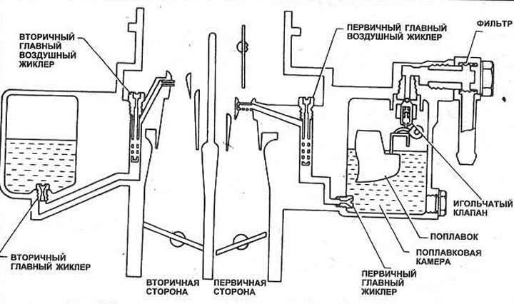
Pic. 3.9. Main carburetor system - typical
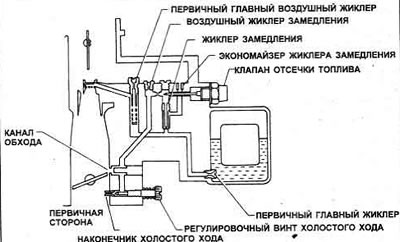
Pic. 3.10. Slow flowing carburetor system - typical
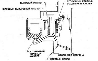
Pic. 3.11. Stepper carburetor system - typical
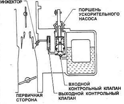
Pic. 3.12. Carburetor Accelerator Pump System - Typical
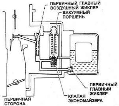
Pic. 3.13. Carburetor Economizer Valve System - Typical
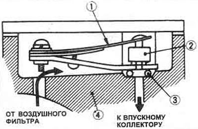
Pic. 3.14. Idle speed compensator components: 1. Bimetallic plate; 2. Rubber valve; 3. O-ring; 4. Carburetor
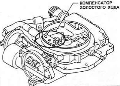
Pic. 3.15. Idle speed compensator location - 1.6 and 1.8 liter models
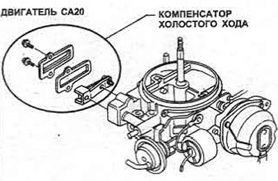
Pic. 3.16. Idle air compensator location - 2.0 liter models
The carburetor includes the following devices:
- Fuel switch valve (fuel cut-off)
- Bimetallic idle speed compensator
- Electrically heated automatic choke accelerator pump
- Deceleration device (manual transmission) (Chapter 18)
- Idle air valve (Chapter 19)
- Throttle dashpot
Fuel cut-off valve prevents operation when ignition is off (diesel effect).
The idle air compensator uses a bimetallic plate to open the air passage from the air filter directly to the intake manifold when the temperature is high enough. It compensates for a rich idle mixture and stabilizes the engine's idle speed.
The automatic air damper consists of a bimetallic coil spring, which (cold) keeps the air damper in the closed position. When the engine rotates, current from the alternator is supplied to the auto damper lamp control relay so that power begins to flow from the battery to the damper assembly. The spring heats up, causing the choke to open. The vacuum chamber opens the air damper, if necessary, in the presence of high vacuum in the manifold.
The dashpot throttle delays the closing of the throttle when the accelerator pedal is lifted, thus allowing any remaining fuel in the manifold to burn.