Electric cooling fan thermal switch
1. Be guided Chapter 10 from this Section for a quick test that should identify defective switches.
2. To carry out a full test, the switch must first be removed from the radiator as follows. First, disconnect the switch wires and check that the engine and radiator are completely cold.
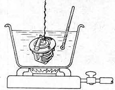
Pic. 2.12. Thermostat test
3. To prevent leaks, drain a small amount of coolant or remove the radiator cap to release residual pressure.
4. On radiators with vertical flow, unscrew the switch from the radiator and quickly plug the hole with a plug; Be careful not to damage the radiator and do not use anything that may leave pieces inside the cooling system. When installing, apply a suitable sealant to the threads of the switch and tighten it securely. Check the coolant level and add if necessary as described in Chapter 2.
5. On cross-flow radiators, turn the switch lock a quarter turn counterclockwise and remove it from the radiator shroud (photo), then remove the switch and discard the rubber seal. Plug the hole. Installation is carried out in the reverse order of removal, always use a new seal.
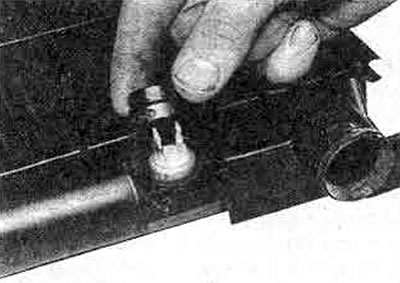
12.5. On a cross-flow radiator, remove the cap from the thermal switch
6. To test the switch, connect an ohmmeter and lower the switch into a pan of heated water (pic. 2.13). Measure the water temperature with a thermometer. Make sure that the switch or thermometer does not touch the tray.
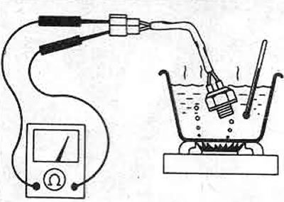
Pic. 2.13. Checking the electric cooling fan thermal switch
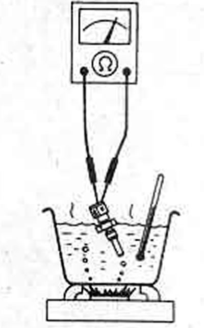
Pic. 2.14. Checking the Water Temperature Sensor - Fuel Injected Models
7. The switch contacts should close when the water reaches the specified temperature. Turn off the heater and let the water cool. The switch should open when the water cools to the specified temperature.
8. Note that switch #1 is installed on the right side of the radiator (above or below) and controls the engine (yami) fan via one or more fan motor relays. Switch No. 2 is installed only on models with a two-speed main fan motor; it is screwed on top on the left side of the radiator.
9. If the switch does not fit within the specified temperatures, it must be replaced.
10. Please note that on carbureted and Turbo models there is a connection from the switch to the idle control system (Section 3).
Coolant temperature sensor (heat transmitter)
11. The coolant temperature gauge installed in the instrument panel is controlled by a sensor (referred to as a heat transmitter in electrical wiring diagrams) which is screwed into the intake manifold behind the thermostat (photo).
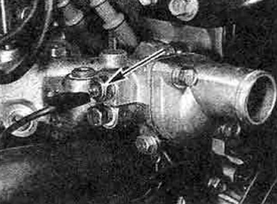
12.11. A Coolant temperature indicator sensor - carburetor models
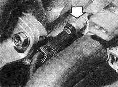
12.11V. Coolant temperature indicator sensor - 2.0 l models. with fuel injection
12. The sensor contains a thermistor, whose electrical resistance decreases according to a certain law as the temperature increases.
13. To quickly check the circuit, turn on the ignition, disconnect the sensor wire and short it to the engine; The temperature gauge arrow should deflect to the maximum position "Hot" and return to position "Cold", if the wire is disconnected from the ground, if the pointer behaves as described, the sensor may be faulty and needs to be checked; if not, there is damage in the indicator or wiring.
14. To check the sensor, unscrew it from the manifold. Plug the hole to prevent refrigerant from escaping.
15. Connect an ohmmeter between the sensor clamp and the sensor body, heat the water and measure the resistance as the temperature rises. Compare the results with the value in the Specifications.
16. If the results are different, the sensor must be replaced.
17. When installing, apply a sealant to the thread of the sensor, carefully tighten it with the tightening force regulated Specification. Check the coolant level, add if necessary; see Chapter 2 of this Section.
Water Temperature Switch - Automatic Transmission
18. All cars with a carburetor and automatic transmission are equipped with a separate thermal switch that is screwed into the intake manifold behind the thermostat.
19. Removal and installation are similar to the procedures described in paragraphs 14 and 17 above.
20. To test the switch, continue as described in step 6 above. The switch contacts should close at approximately normal operating coolant temperature.
21. If the switch is faulty, it must be replaced.
Water temperature sensor - Turbo and 2.0i GSX models
22. To control the engine temperature, the control unit receives a signal from a temperature sensor, which is screwed into the thermostat housing (photo). The unit is controlled by the refrigerant temperature.
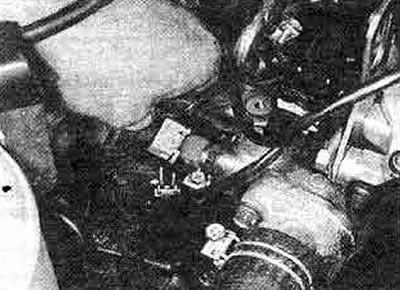
12.22. Disconnecting the temperature sensor - 2.0 l models. with fuel injection
23. The sensor contains a thermistor, the electrical resistance of which decreases according to a certain law as the temperature increases.
24. Remove and install the sensor as described in steps 14 and 17 above (photo).
25 To quickly check the sensor, disconnect the wires and measure the resistance at the sensor terminals on a completely cold engine. Reconnect the sensor, start the engine, and warm it up to normal operating temperature. Stop the engine, disconnect the sensor wires and measure the resistance again; The resistance should be much lower and correspond to the values specified in the Specifications.
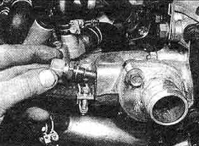
12.24. Removing the temperature sensor for the 2.0 l model. with fuel injection
26. To fully test the sensor, remove it and connect the multimeter across the clamps, then lower the sensor into a tray of heating water (pic. 2.14). When using a thermometer, monitor the temperature and do not allow the probe or thermometer to touch the pan. As the water heats up, note the corresponding resistance data and compare it with that shown in Specifications.
27. If the sensor is faulty, replace it.