If these checks do not reveal the cause of poor engine performance, the carburetor must be removed for cleaning and repair.
Carburetor disassembly is usually required very rarely. In most cases, only cleaning of the jets and internal channels is required.
Disassembly
1. Disconnect the throttle spring and check the accelerator pump lever for wear.
2. Remove the spring, spring and retaining rings and remove the lever.
3. Disconnect the air damper rod.
4. Loosen the screws and carefully remove the upper housing section.
5. Check for dirt in the float chamber.
6. Remove the first accelerator pump spring, retaining ring, filter and remove the ball.
7. Unscrew the plug and remove the second accelerator pump spring, counterweight (check valve) and a ball.
8. Remove the pump piston and check the wear of the piston and cylinder.
9. Knock out the float shaft, remove the float, needle valve and float chamber gasket (on some carburetors, the needle valve seat cannot be removed).
10. Before disassembly, remember the location of all jets.
11. Turn out all fuel and air jets from both chambers; idle air jets of the secondary chamber must not be turned out.
12. Remove the plugs and idle jets from the middle section of the housing.
13. Loosen the screws and remove the small diffusers, remove the emulsion tubes.
14. Unscrew the main jet of the primary chamber from the wall of the float chamber.
15. Turn out the main jet of the secondary chamber.
16. Remove the stop sleeve and tighten the screw until it touches the hole, counting the number of turns.
17. Loosen the screw completely.
18. If necessary, you can unscrew the valve coils, carefully remove the seals and springs.
19. Check the coils - when 12V is applied, the plungers should retract.
20. On vehicles with a converter, if necessary, the mixture maintenance valve can be removed by disconnecting the wire, unscrewing the screws and removing the valve.
21. Clean the jets using special tools (blowing with compressed air is not recommended, as the carburetor diaphragms can be damaged).
22. Rinse body parts.
23. Check the curvature of the split planes of the body sections.
24. If it is necessary to remove a part of the carburetor electrical equipment, disconnect the wire of this part from the connector.
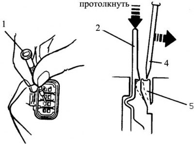
25. To do this, use a thin screwdriver (1, 4) remove the output tab (5) and push through the lead with the wire (2), first remove the retaining ring at the back of the connector.
26. Label each wire.
27. When assembling, replace worn parts and the entire set of gaskets and seals.
28. Assembly is carried out in the reverse order.
29. Do not overtighten the jets.
30. Make any necessary adjustments before installing the carburetor.
Adjustment of turns of idling and quality of a mix
See subsection 2.2.2.
Adjusting the fuel level in the float chamber
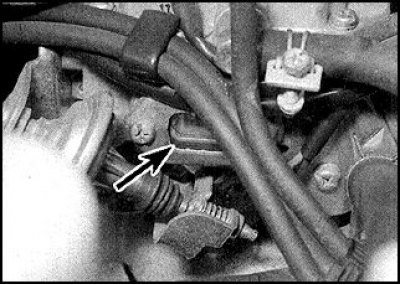
The arrow indicates the viewing window in the carburetor body.
Attention! The fuel level in the float chamber can be checked through the sight glass. At idle, the level should be between the two marks.
1. Level adjustment is as follows.
2. Raise and lower the float onto the needle valve and measure the distance between the float and the plane of the carburetor body.
3. If the distance differs from the norm, then adjust by carefully bending the axle lever.
4. Turn the carburetor body over and check the distance between the lower edge of the float and the split plane.
5. If the distance differs from the norm, then adjust by carefully bending the tab of the limiter.
Throttle valve angle adjustment
1. Loosen the three screws and remove the thermal actuator and ring.
2. Turn the carburetor over, open the throttle slightly, and move the high idle lever to the second cam stage. Due to the adjusting screw, the damper will be slightly ajar.
3. Make sure the air damper is fully closed.
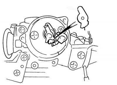
4. Move the high idle lever to the second cam stage.
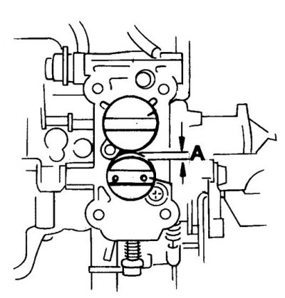
5. Check the clearance with a drill (A) between throttle valve and chamber wall.
6. If necessary, set the gap by turning the adjusting screw.
7. Install ring and thermoelectric drive.
8. Align the marks on the top of the actuator and on the damper body, tighten the screws.
Air damper adjustment
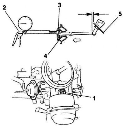
1. Tongue; 2. Vacuum pump; 3. Pneumatic drive; 4. Aperture; 5. Clearance
1. Pull the linkage and fully close the choke.
2. Fully push the stem into the diaphragm using a screwdriver, or by creating a vacuum in the diaphragm.
3. Check the gap between the air damper and the chamber wall with a drill (at temperatures below 5°C, use the gap value for the 1st position as a control, above 16.5°C - for the 2nd position).
4. If necessary, adjust the gap by bending the tongue.