Table of operation of the gear shift mechanism
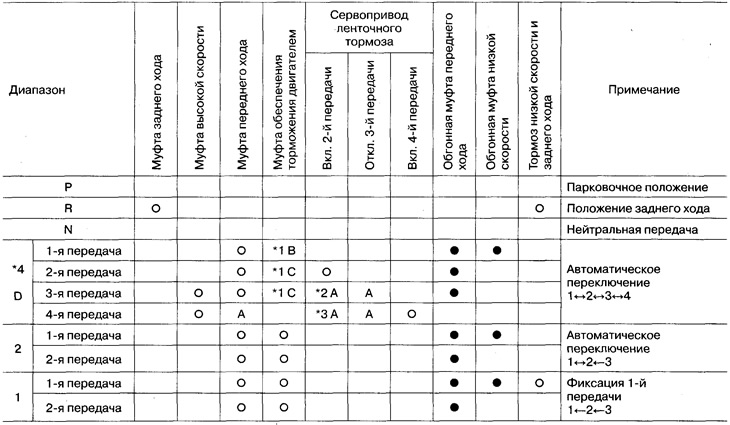
*1: Operates when the overdrive switch is set to «OFF» (switching to position D is blocked4)
*2: Oil pressure is applied both to the side «inclusion» 2nd gear, and «blackouts» 3rd gear piston servo belt brake. However, the brake band does not compress because side oil pressure area «blackouts» more than from the side «inclusion».
*3: Oil pressure is supplied to the side «inclusion» 4th gear is subject to *2 above and the brake band is compressed.
*4: The automatic transmission will not shift to 4th gear when the overdrive switch is moved to the «OFF» (off).
o: It works.
•: Works when accelerating.
A: It works, but power is not transmitted.
Q: Works when the accelerator pedal is depressed less than a certain amount, there is no engine braking.
C: Works when the accelerator pedal is depressed less than a certain amount, there is engine braking.
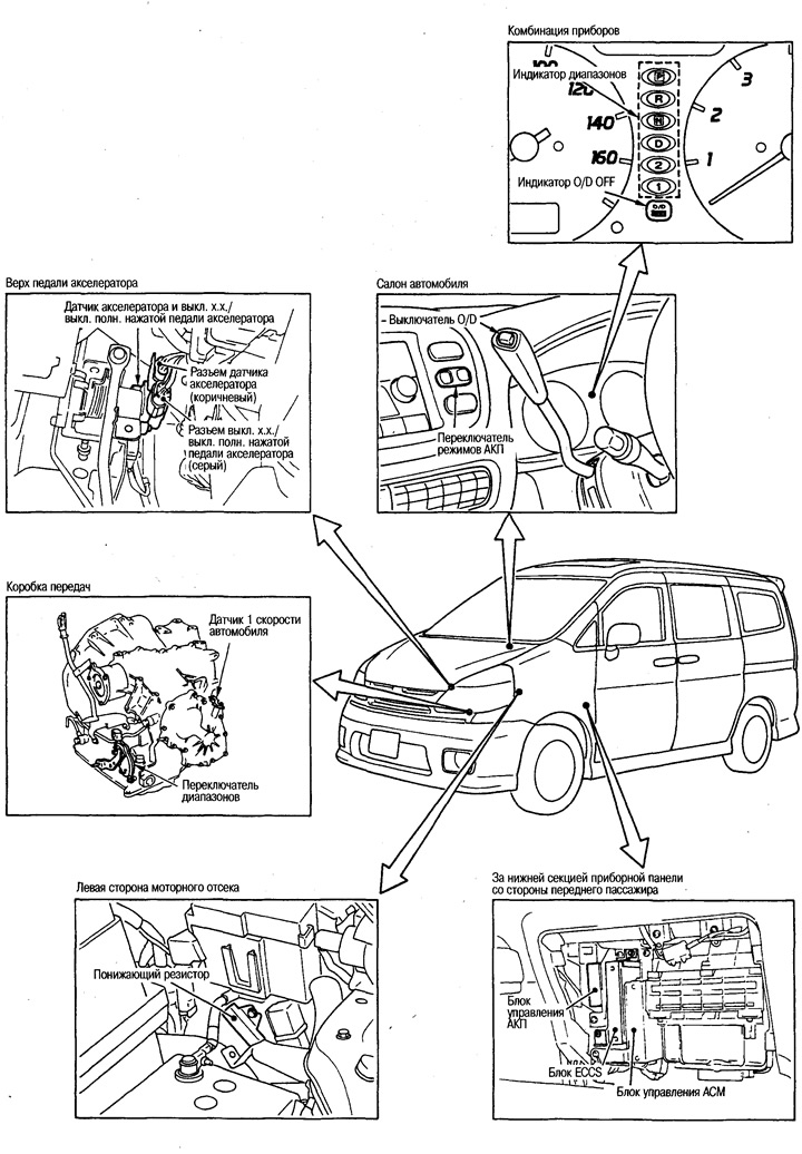
Location of components
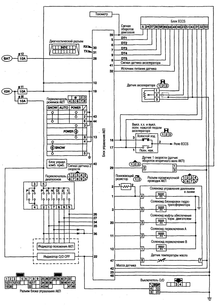
Wiring diagram
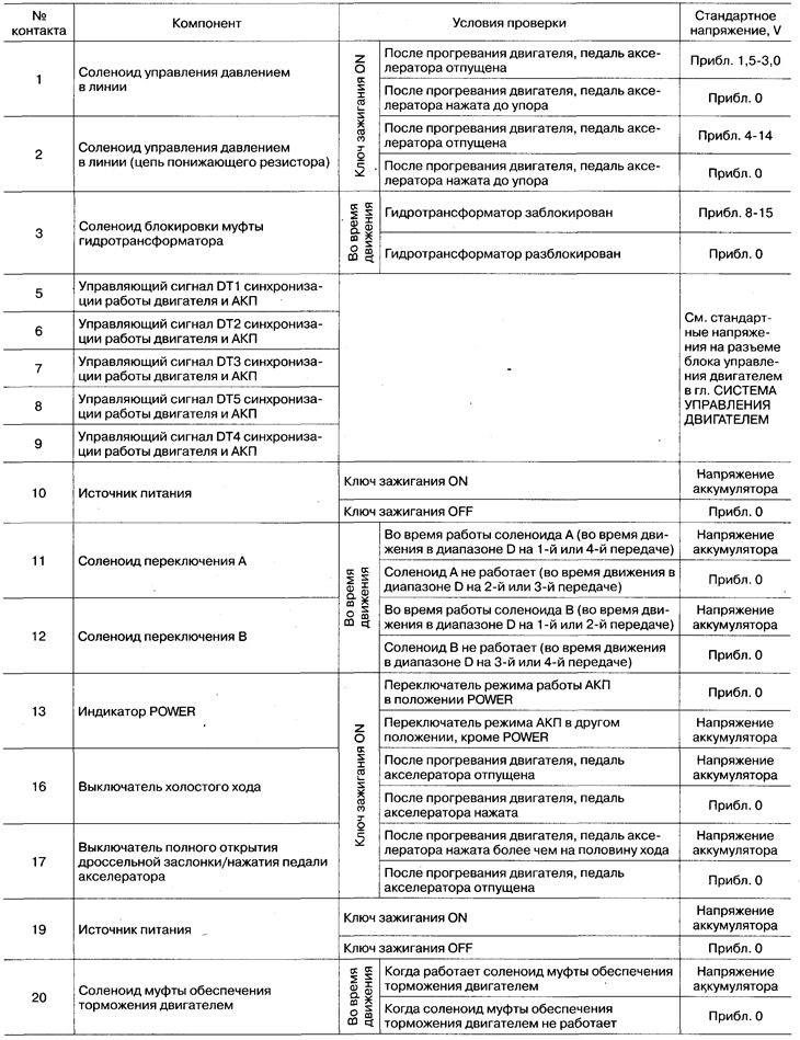
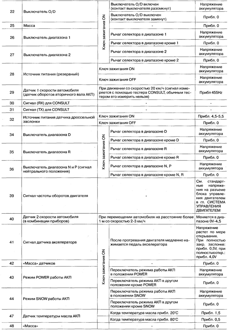
Standard voltage input/output signals on the contacts of the connector of the automatic transmission control unit

Gear change charts
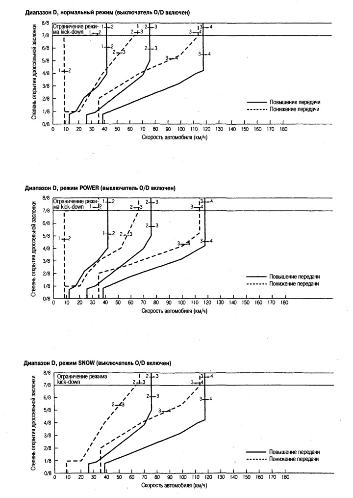
Gearshift table depending on the speed

Vehicle speeds when torque converter lockup occurs

Shows vehicle speeds in D range while driving in 4th gear.
The pedal depressed state refers to the state when the idle switch is OFF and the accelerator pedal is depressed 1/8 full travel or less.
The half-pressed state of the pedal refers to the state when the accelerator pedal is depressed 4/8 of its full travel.