
Preparatory work
Relieve fuel pressure.
Remove the engine protection from the bottom.
Drain the coolant.
Remove the front exhaust pipe.
Remove the air duct, air cleaner housing and resonator.
Remove the fuel pipe.
Remove the complete injectors.
Remove all electrical wiring and tubing connectors and move to the side.
Removal and installation of the throttle chamber
Removing
Loosen the screws in the reverse order shown in the figure.
Installation
Tighten the bolts in two stages in the order shown in the figure.
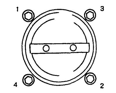
First stage:
Second phase:
Attention: After replacing the throttle body, start the air supply learning procedure at idle speed, see ch. engine management system.
Removal and installation of an inlet collector assy
Removing
1. Remove the 2 water tube bracket bolts from the rear.
2. Remove the components from the right side, see fig.
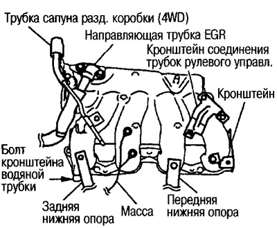
3. Remove the front and rear lower supports.
Unscrew the mounting bolts from above and loosen the fasteners from below.
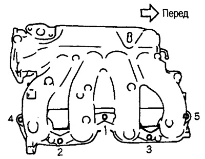
4. Remove nuts and bolts in the reverse order shown in the figure.
Installation
Tighten the nuts and bolts in the order shown in the figure.
Removing and installing intake manifold adapter
Removing
1. Loosen the fixing bolts of the water tube center bracket.
2. Remove the heater tube.
3. Disconnect the connectors from the temp sensor. cool. fluid and temp. cool. liquids.
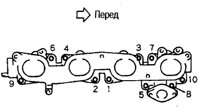
4. Remove the bolts and nuts in the reverse order shown in the figure.
Installation
Tighten the bolts and nuts in the order shown in the figure.
Removal and installation of the AAC valve
Removing
Note: Do not unscrew the 2 valve fixing screws.
Installation
Attention: After replacing the throttle chamber, start the air supply learning procedure at idle speed, see Ch. engine management system.
Intake Manifold and Adapter Warping Check
Use a feeler gauge to check for warping of the contact surface.
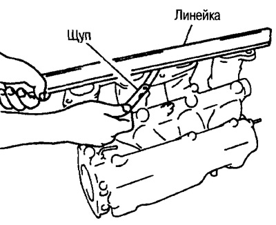
- Limit Warping: 0.1mm