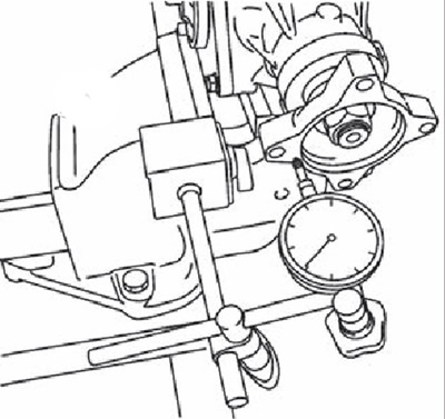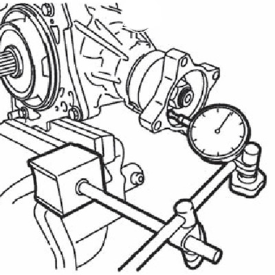
2. Rotate the connecting flange to check for runout.
Note. Flange runout (surface on the inside of the bolt holes): 0.15 mm.
3. Install the dial indicator probe on the inside of the flange (nest).

4. Rotate the connecting flange to check for runout.
Note. Flange runout (socket for fixing flange nut): 0.2 mm.
5. If the values obtained are not correct, do the following:
- Check the runout of the flange by turning the flange by 90°. Select the installation position with minimum runout.
- Replace the connecting flange with a new one if the zone runout is still out of specification.
- Adjust or replace the pinion shaft bearings if the runout is not correct even after the flange has been replaced.
Attention. In each case of adjustment or replacement of the connecting flange, it is necessary to replace the composite spacer with a new one.