Carburetor models 4.2 l and 3.0 l
All models are equipped with a TX12A transfer case mounted at the rear of the transmission and allowing the driver to directly drive the vehicle's front wheels in overdrive or downshift modes. The selection is made using a lever located on the wall of the transmission and connected to the transfer case control lever by means of a shift rod. To enable the operation of the power take-off (RTO) (if provided) the selector lever can be moved to the position "N".
The transfer box assembly consists of front, center and rear crankcases and contains input, driven and front output shafts rotating in roller bearings. To avoid loss of lubricating fluid, the crankcases are equipped with oil seals.
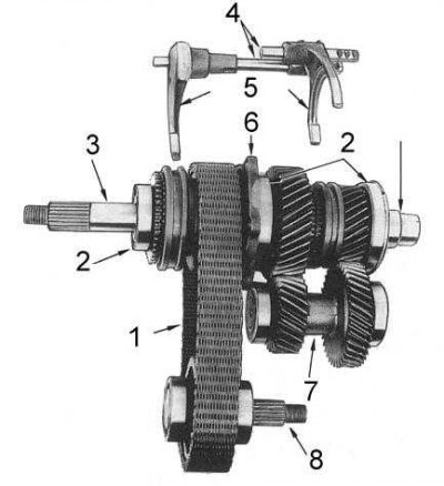
Transfer case components

1 - drive chain; 2 - bearing; 3 - driven shaft; 4 - switching rods; 5 - switching forks; 6 - holder; 7 - input shaft; 8 - intermediate shaft; 9 - front output shaft
Rotation is transmitted from the rear of the driven shaft of the gearbox to the splines of the input shaft. The overdrive mode is engaged by moving the sliding splined clutch forward, resulting in direct engagement of the input shaft with the output shaft. Shifting the clutch back disengages the shafts from direct engagement and articulates them through the reduction gear. In this case, the rotation is transmitted from the input shaft to the downshift gear through the intermediate shaft. The intermediate shaft is equipped with spring-loaded gear rings at both ends to select the backlash.
The drive to the front wheels is carried out by engaging the drive sprocket and the clutch gear of the driven shaft through the internal splines of the synchronizer clutch, articulating the synchronizer teeth with the clutch gear. Synchronization is carried out when the synchronizer ring contacts the cone on the wall of the clutch gear. At the same time, the speeds of rotation of the drive sprocket and gear are compared and smooth shifting is achieved. The drive chain is used to transfer power from the drive sprocket to the front output shaft.
4.2L EFI Models
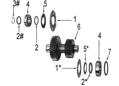
The transfer case differs from the TX12A discussed above in the absence of a spring-loaded gear ring, a belleville spring and a spacer ring at the rear end of the intermediate shaft. Models since December 1992 also missing the circlip and spacer at the front end of the layshaft (see accompanying illustration) - components fixed since 10.91 are marked with *, fixed since 12.91 - #.

1 - gear ring; 1* - gear ring; 2 - remote ring; 2# - distance ring; 2* - remote ring; 3# - retaining ring; 4 - bearing; 5 - disc spring; 5*— Belleville spring; 6 - intermediate shaft; 7 - adjusting washer
From August 1995, the spacer at the forward end of the input shaft and the spacer near the output shaft center bearing were eliminated.
Transfer case maintenance procedures are the same for all models.