Note. The following special tools are required to perform the procedures below: 53mm replacement socket (models with manual hub shifting), or homemade nozzle (models with automatic drive) - for loosening and tightening the wheel bearing nut.
Removal and disassembly
1. Loosen the front wheel nuts.
2. Jack up the front of the car and place it on jack stands under the frame side members. Remove the front wheel.
3. If it is necessary to replace the drive shaft, remove the drain plug and drain the oil from the front axle housing of the vehicle.
4. Give fixing bolts and remove a support of the brake mechanism from a rotary fist. Tie the caliper to the side to the suspension element, making sure that the brake hose is not stretched and turned out to be twisted.
5. On models with manual hub shifting (hub components are shown in the accompanying illustration):
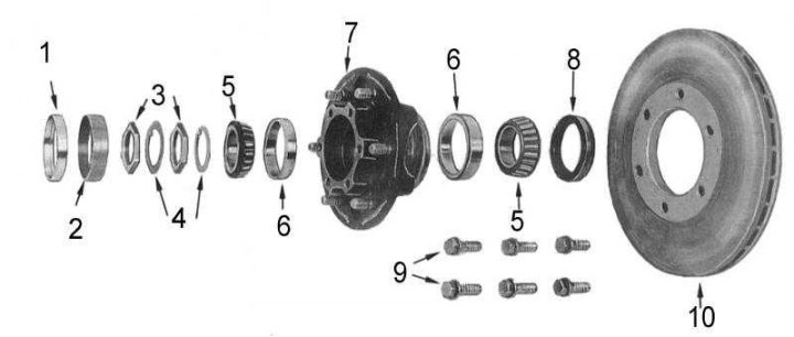
1 - bushing; 2 - remote ring; 3 - nuts; 4 - washers; 5 - bearing; 6 - cup; 7 - hub; 8 - stuffing box; 9 - brake disc; 10 - bolts
- Release hub drive (FREE position), give fixing bolts and remove the drive from the wheel hub.
- Remove the circlip from the end of the drive shaft and remove the drive sleeve.
- Remove the bushing and spacer from the wheel hub. Unbend the lock washer flag and use a 53 mm replacement head to release the wheel bearing lock nut. Discard the lock washer, unscrew the hub nut and remove the washer from the stub axle.
6. On models with automatic hub shifter:
- Switch the drive to the LOCK position, give the fixing bolts and remove the drive from the wheel hub. Remove and discard the O-ring.
- Remove the retaining ring from the end of the drive shaft and remove the inner brake assembly.
- Loosen the lock washer mounting screws, remove the lock plate and unscrew the hub nut on the stub axle using a specially made tool (see accompanying illustration).
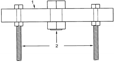
1 - steel plate
2 - bolts
7. Remove the hub and disc assembly from the stub axle. Be careful not to drop the outer bearing cone while doing this.
8. Using a suitable lever or screwdriver, remove the oil seal from the inside of the hub and discard it. Remove the inner bearing cone as well.
Note. If the wheel bearings are removed only for repacking with grease, there is no need to remove their cups, and therefore the procedure of the next paragraph can be omitted.
9. Support the hub assembly and use a brass drift to knock out the inner and outer bearing cups from it. The extraction of the inner cup is made from the inner end of the hub, the outer one - from the outer one.
10. Mark position of a nave concerning a brake disk, then give fixing bolts and separate a disk from a nave.
11. Give bolts of fastening of a brake board and a rotary fist to a rotary pin, then remove anther with a board.
12. Using a soft-faced hammer, knock out the trunnion from the steering knuckle.
13. With the steering knuckle in a straight position, remove the drive shaft from the axle housing. Remove the thrust washer from the shaft.
14. Remove the oil seal from the back of the stub axle, then use a drift to remove the drive shaft support bearing (stub axle components are shown in the accompanying illustration). Discard the bearing.
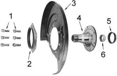
1 - bolts; 2 - anther; 3 - brake shield; 4 - pivot pin; 5 - stuffing box; 6 - bearing
15. Using a hammer with a sliding head, remove the drive shaft inner oil seal from the axle housing (see accompanying illustration).
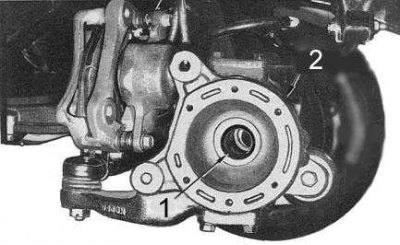
1 - stuffing box
2 - axle housing
16. If necessary, disassemble the hub shift drive assembly (see accompanying illustration):
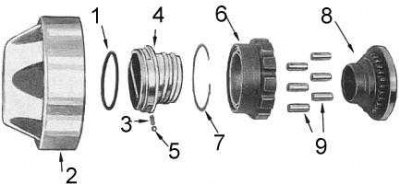
1 - sealing ring; 2 - casing; 3 - spring; 4 - switch handle; 5 - ball; 6 - clutch; 7 - retaining ring; 8 - drive clutch; 9 - rollers
Note. It is good practice to periodically disassemble, inspect, and lubricate the shift actuator components with a lithium-based multipurpose grease.
Note. The automatic switching drive unit cannot be disassembled and, in case of failure, is replaced entirely.
- Mark the position of the hub shift housing in relation to the clutch.
- Turn the cover over, remove the rollers and unscrew the clutch.
- Using a flat-blade screwdriver, remove the retaining ring securing the shift knob to the cowl. Knock the handle out of the casing, being careful not to drop the ball with the spring.
Cleaning and checking the condition of components
1. Wash all components except seals in cleaning solvent and dry with compressed air.
Note. To avoid personal injury or damage to the bearings, do not rotate them with compressed air.
2. Check the roller bearings and their cups for cavities, signs of wear and damage. Replace if necessary.
Note. It is not possible to replace individual bearing components individually, therefore, in case of defects, the bearing assembly is replaced.
3. Check the condition of the threads at the end of the stub axle and in the hub nut.
4. Check the hub for cracks or other damage.
5. Inspect the drive shaft for cracks and signs of spline wear. Assess the freedom of rotation of the CV joint with the outer drive shaft turned at an angle.
Note. If the drive shaft or CV joint is found unfit for further use, it is necessary to replace them as an assembly.
6. Check the thrust washer and hub nut for cracks and signs of wear.
7. Inspect the hub shift housing for cracks or other damage. Check the freedom of movement in the clutch housing.
8. Check the condition of the sealing ring in the manual drive, replace the ring if necessary.
Note. If any components of the manual hub shift drive other than the clutch gear are found to be faulty, the drive assembly should be replaced. Vehicle manufacturers do not impose any special requirements on the replacement retaining ring.
9. Replace defective components.
Assembly and installation
Note. Unless specifically stated in the description of the procedure, the type of grease used is assumed to be a lithium-based general purpose grease.
1. Using a suitable drift, install the inner oil seal into the axle housing. Fit the gland flush with the edges of the undercut. Lubricate the seal lips.
2. Pack the driveshaft CV joint with lithium-based molybdenum disulphide grease, insert the shaft into the axle housing and engage it with the differential splines. Be careful not to damage the internal shaft seal during this procedure.
3. Lubricate the thrust washer and slide it onto the drive shaft.
4. Using a suitable drift, install a new driveshaft support bearing and oil seal into the rear of the stub axle. Lubricate installed components.
5. Install the stub axle assembly on the drive shaft and steering knuckle. Tap the assembly until seated with a soft-faced hammer.
6. Lubricate the boot, install the brake shield with boot on the pivot pin and tighten the fixing bolts with a force of 30÷40 Nm.
7. Install the brake disc on the hub, making sure that the marks of the relative position made during the dismantling process are aligned. Tighten the fixing bolts with a force of 50÷68 Nm.
8. Using a brass drift, install the bearing cups into the hub (constrictions outward and in different directions).
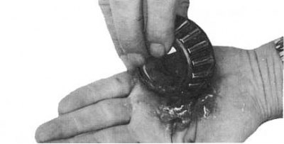
9. Pack the cones of the inner and outer bearings with high-temperature lithium-based grease, carefully packing the roller space, inner race, and cage with it (see accompanying illustration).
10. Install the inner bearing cone into the hub, then seat the hub seal flush with the end of the latter taper to the bearing. Lubricate the seal lips.
11. Pack the cavity in the hub between the bearing cups with high-temperature lithium-based grease and slide the hub onto the stub axle.
12. Support the hub assembly and install the outer bearing cone.
13. On manual hub shift models, install the lock washer on the stub axle.
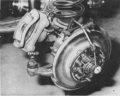
14. Lubricate the surface of the hub nut and adjust the bearing preload:
- Tighten the nut with a force of 167÷196 Nm, turn the wheel hub several times in different directions, then completely loosen the nut.
- Tighten the nut with a force of 3÷5 Nm, rotate the hub several times in both directions and tighten the nut again with a force of 3÷5 Nm. Again rotate the hub in different directions.
- Fix the dial gauge by leaning its plunger against the surface of the hub and measure the value of the axial play of the hub (see accompanying illustration). If the measurement result exceeds 0.08 mm, remove the hub assembly and check that the bearings are installed correctly and the nut is screwed on (did it warp on the thread).
15. On models with an automatic shift drive, install the lock plate and firmly tighten the screws securing it.
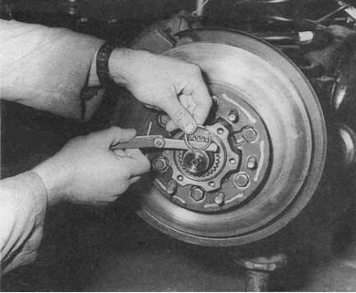
16. On manual models, perform the following procedures:
- Lubricate a new thrust washer, put it on the pivot pin, screw on the lock nut and tighten it with a force of 167÷196 Nm.
- Apply at least six grams of grease to the inner walls of the bushing, then use a soft-faced hammer to drive the spacer ring and bushing into the hub.
- Apply at least six grams of grease to the outer edge of the drive coupling flange and install the coupling onto the stub axle.
- Grab the end of the drive shaft and pull it out of the stub axle. Insert the retaining ring into the groove at the end of the shaft, then use a blade-type feeler gauge to measure the end play of the shaft. The play should not exceed 0.2 mm. If necessary, replace the retaining ring with a new one of the appropriate thickness.
Note. The old ring is replaced without fail.
- Thoroughly lubricate the hub shift drive components.
- Put on a new sealing ring on the shift knob. Insert the spring and ball into the handle, then seat it in the casing, making sure that the ball enters the groove. Install retaining ring.
- While holding the knob in the LOCK position, screw the clutch into the housing until the drive gear is flush with the shoulders machined inside the upper end of the housing (see accompanying illustration), and the landing marks applied during the dismantling were combined.
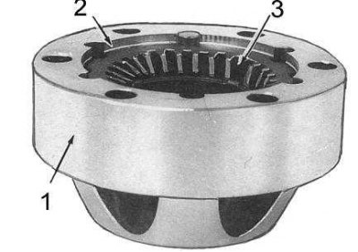
1 - casing; 2 - hangers; 3 - drive gear
- Lubricate the end of the drive shaft and, with the handle in the FREE position, install the hub shift actuator assembly onto the drive shaft. Tighten the fixing bolts with a force of 54÷59 Nm and check the smoothness of the drive switching.
17. On models with automatic hub shifting drive:
- Slide the inner brake assembly and washer onto the drive shaft.
- Grab the end of the drive shaft and pull it out of the stub axle. Insert the retaining ring into the groove at the end of the shaft, then use a blade-type feeler gauge to measure the end play of the shaft. The play should not exceed 0.2 mm. If necessary, replace the retaining ring with a new one of the appropriate thickness.
Note. The old ring is replaced without fail.
- Lubricate the inner brake assembly and the inner part of the hub shift actuator assembly.
- Switch the drive assembly to the LOCK position and lightly press it against the front hub, making sure that the protruding ends of the wire clamp are not aligned with the protrusions of the drive release brake. If necessary, remove the drive assembly if it cannot be pressed firmly against the front hub.
- Screw in the fixing bolts and tighten them with a force of 54÷64 Nm.
18. Install the brake caliper and tighten its fastening bolts with a force of 72 ÷ 79 Nm.
19. Fill the front axle housing with the required amount of oil of the required grade (see tables of sizes and adjustments at the end of the guide).
20. On models with automatic front wheel hub shift, engage 4WD and shift the transmission into gear. Shift the drive to the AUTO position and, to release the hubs, rotate each of the front wheels alternately in both directions while holding the opposite one stationary.