Removal and disassembly
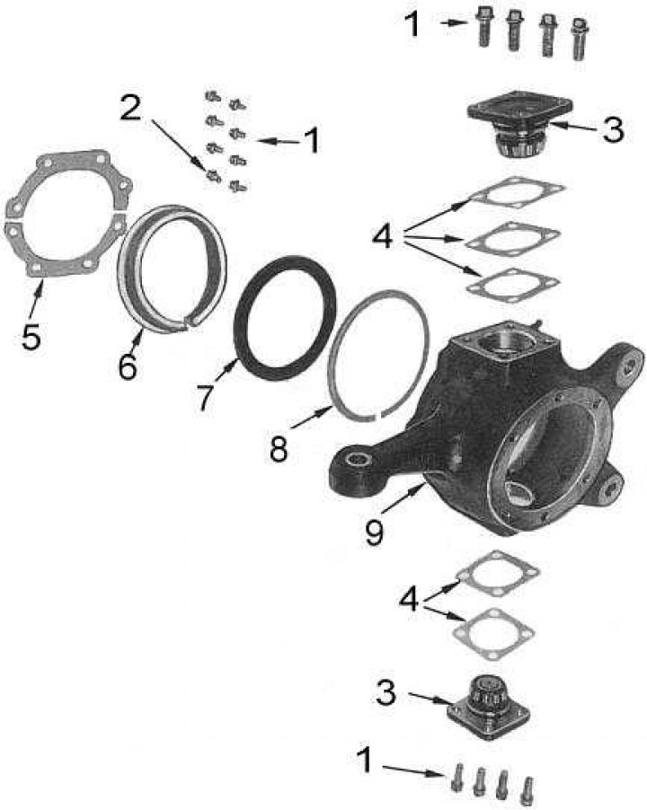
Steering knuckle assembly components

1 - bolts; 2 - thrust bolt; 3 - cover; 4 - shims; 5 - shield; 6 - wiper; 7 - stuffing box; 8 - support ring; 9 - knuckle
1. Loosen the front wheel nuts.
2. Jack up the front of the car and place it on jack stands under the frame side members. Remove the front wheel.
3. Remove the wheel hub and drive shaft.
4. Remove the cotter pin and give the castellated nut of the ball joint (ov) tie rod end (rods) to the knuckle arm. Attach a tamper or a hammer head to the ear of the rotary lever and, tapping on the ear from the opposite side, knock out the pin from the lever (And) ball joint (ov).
5. Give bolts of covers of the top and bottom bearings and remove assemblies of covers with adjusting linings from a rotary fist. Mark the covers and gaskets - they must be installed in their original positions during assembly.
6. Give bolts of fastening of a guard of an epiploon. try to remember the installation position of the turning lock bolt and the number of turns required to turn it out. Remove shields.
7. Remove the steering knuckle from the axle housing trunnion, then remove the support ring, oil seal and wiper.
8. Using a drift, remove the cups of the upper and lower bearings and the plug from the bridge trunnion.
Cleaning and checking the condition of components
1. Wash all components except seals in cleaning solvent and dry with compressed air.
Note. To avoid personal injury or damage to the bearings, do not rotate them with compressed air.
2. Check the bearings and their cups for cavities, signs of wear and damage. Replace if necessary.
3. Inspect the steering knuckle and axle housing trunnion for signs of wear, cracks, or other damage. Remove small burrs with a grindstone.
4. Check the gland, seals and wiper for cracks or other damage.
Note. The compilers of this Guide recommend replacing the oil seal and steering knuckle wiper, regardless of their condition. If the bearing cap seal needs to be replaced, the bearing cone must be removed from the cap.
5. Replace any defective components.
Assembly and installation
Note. Unless specifically stated in the description of the procedure, the type of grease used is assumed to be a lithium-based general purpose grease.
Assembly is carried out in the reverse order of dismantling.

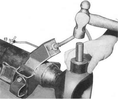
1. Install new plugs and cups of the upper and lower bearings in the bridge trunnion, using a tubular drift for this purpose (see accompanying illustration).
2. Lubricate the lips and the outer wall of the steering knuckle oil seal and put the wiper, oil seal and support ring on the axle axle.
3. Lubricate the axle trunnion and install the steering knuckle on it. Do not install the oil seal in the knuckle at this stage of assembly.
4. Pack the cones of the upper and lower bearings with grease, install the bearing assemblies and shims on the steering knuckle (to their former positions) and firmly tighten the fixing bolts.
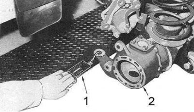
5. With the steering knuckle in a straight position, hook the steelyard onto the eye of the swing arm, positioning it at a 90°angle to the arm approximately 170mm from the axle centerline (see accompanying illustration).

1 - steelyard
2 - steering knuckle
6. Measure the force required to turn the knuckle on the bridge trunnion. If the measurement result is outside the range of 0.6 ÷ 1.75 kG, correct by selecting the adjusting shims of the cups of the upper and lower bearings of a new thickness.
Note. Make sure that the total thickness of the shims of the upper and lower covers are the same in order to avoid misalignment of the position of the steering knuckle.
7. Tighten the bearing cap bolts with a force of 30÷40 Nm. Apply about 50 g of grease to the outer surface of the oil seal and wiper, as well as the mating surfaces of the steering knuckle.
8. Install the support ring, oil seal and wiper assembly into the steering knuckle, make sure that the lock slots of the support ring and wiper are at the bottom of the fist assembly. Install the shields and the swivel lock bolt to their original positions.
9. Connect the ball joint (s) tie rod (rods) to the swing arm and tighten the castle nut (And) with a force of 46÷54 Nm. Install a new cotter pin (s).
10. Reinstall the wheel hub and drive shaft.