Examination
Note. Performing the procedure described below may lead to the entry into the OBD memory of a malfunction, which will be highlighted by a control lamp "Check engine". After completing the check and the corresponding remedial repair, do not forget to clear the system memory (see Section On-Board Diagnostic System (OBD) - the principle of operation and fault codes).
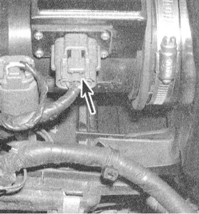
1. Before proceeding to check the MAF sensor itself, make sure that the power supply to it is working properly and evaluate the quality of the ground.
2. Disconnect the wiring from the MAF sensor. And connect the positive probe of the voltmeter to the white-black terminal (1993 and 1994) /red (since 1995) connector wires. Ground the negative probe to ground. Turn on the ignition (do not start the engine), - the meter should register a voltage close to the battery voltage, otherwise check the condition of the ECCS relay and the circuit of the corresponding electrical circuit (see wiring diagrams at the end of the Chapter Onboard electrical equipment).
3. On 1993 and 1994 models. issue check the grounding of the harness black wire terminal - there should be continuity to ground.

4. Restore the original wiring connection to the MAF sensor and probe the positive probe of the voltmeter on the white wire terminal on the back of the connector (ground the negative probe of the voltmeter to ground) (see chapter Onboard electrical equipment). With the ignition on (do not start the engine) there should be a voltage of about 0.5 (1993 and 1994) /1.0 (since 1995) IN.
5. Start the engine at idle and repeat the measurement - this time the device should register a reading of 1.0 ÷ 1.7 V. With an increase in engine speed, the signal voltage should also increase (up to 3.0 V). Unfortunately, in a garage it is not possible to simulate the operation of an engine under load, however, the dependence of voltage on speed described above should be absolutely clear.
6. Positive results of the test described above confirm the health of the MAF sensor. Now you should check the wiring of the sensor circuit for signs of breaks. If no deviations can be detected, the car should be driven to a service station for diagnostics and appropriate reconditioning of the PCM.
Note. More in-depth diagnosis of the MAF sensor (some deviations cannot be detected with a voltmeter) can also be produced in a service station.
Replacement
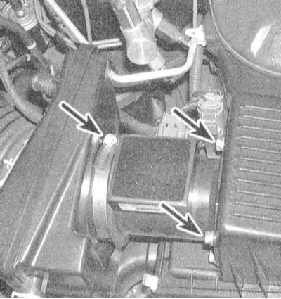
Note. The MAF sensor placed in a plastic housing is replaced complete with a metal air intake sleeve, inside of which it is fixed. Do not attempt to remove the sensor from the sleeve.
1. Disconnect the wiring from the sensor.

2. Loosen the clamp that secures the sensor in the air intake sleeve and unscrew the four fixing screws.
3. Install a new sensor and connect the wiring to it.