Disassembly
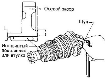
1. Before removing parts from the secondary shaft, measure the axial clearance of driven gears 1st, 2nd. 3rd and 4th gears. Clearance values are given in section «Data for adjustments and control». If the clearance is not within the specified limits, disassemble the shaft and inspect the contact surfaces of the gear, shaft and synchronizer hub. Then check the gap between the half rings and the shaft groove.
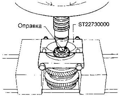
2. Press the output shaft front bearing.
3. Press the output shaft rear bearing using the same tools as for the front bearing.
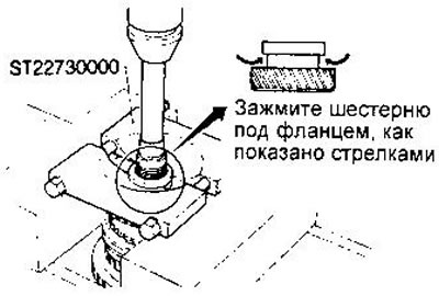
4. Remove the half ring holder, half rings and thrust bushing.
5. Press the 5th driven gear.
6. Remove the 4th driven gear, its bushing and steel ball. Be careful not to lose the ball.
7. Remove the 3rd and 4th gear synchronizer, 3rd driven gear, 2nd and 3rd gear bushing, ball and 2nd driven gear.
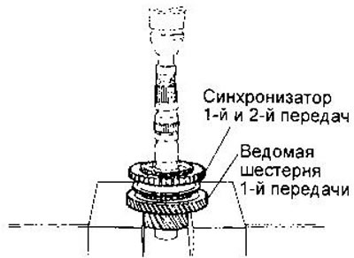
8. Remove the 1st and 2nd gear synchronizer, 1st gear driven gear and needle bearing.
Examination
See section «input shaft».
Assembly
1. Assemble synchronizers 1-2 and 3-4 gears. Please note that the ends of the return springs must be hooked on different crackers.
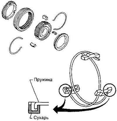
2. Install the needle bearing and 1st driven gear.
3. Press the 1st and 2nd gear synchronizer onto the shaft using tool ST22452000.
4. Install the steel ball, 2nd driven gear, 2nd and 3rd gear hub, 3rd driven gear and press on the 3rd and 4th synchronizer using tool ST37750000. Before installing the ball, lubricate it with multipurpose grease. The 2nd and 3rd gear bushing has a groove; which the ball must be included.
5. Install the 4th gear ball, bushing and driven gear.
Before installing the ball, lubricate it with multipurpose grease. The 4th gear bushing has a groove in which the ball must fit.
6. Press on the 5th driven gear using tool 'ST37750000'.
7. Put on the stop sleeve.
8. Install the half rings, selecting them so that the gap between the ring and the groove is 0-0.1 mm. Available ring sizes are listed in section «Data for adjustments and maintenance».
9. Install half ring holder.
10. Press the rear bearing onto the output shaft using tool ST22360002.
11. Press on the front bearing.
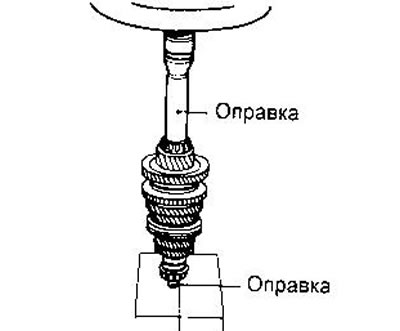
12. Measure the axial clearances of the gears (see subsection «Disassembly»).