Examination
Check the bearings with the engine warm.
1. Remove the cylinder head cover.
2. Remove all spark plugs.
3. Set the piston of the 1st cylinder to the TDC of the compression stroke according to the mark on the crankshaft pulley.
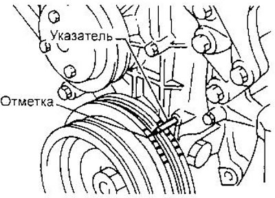
Valve tappets of the 1st cylinder must be free (valves closed), and the pushers of the 4th cylinder are pressed (valves open). If not, turn the crankshaft one revolution and align the mark on the pulley with the pointer again.
4. In this position and the crankshaft, check the clearances of the valves shown in the figure.
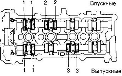
To check, insert a blunt between the valve lifter and the back of the camshaft cam. Make a note of any gaps that are not within tolerance. You will need them when selecting shims.
Clearances on a warm engine:
- Inlet valves - 0.21-0.49 mm
- Exhaust valves - 0.30-0.58 mm
5. Rotate the crankshaft one revolution (360s) and again align the mark on the pulley with the pointer.
6. Check up backlashes of the valves shown in drawing.
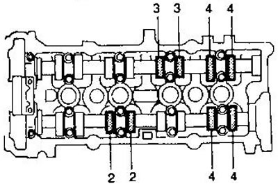
7. If all clearances are correct, reinstall the cylinder head cover and spark plugs.
Adjustment
Clearance adjustment is carried out on a cold engine.
1. Rotate the crankshaft so that the cam of the valve to be adjusted is pointing up.
2. Grasp the camshaft with a special tool (A). Before doing this, turn the tappet so that the notch faces the center of the cylinder head. This will make it easier to remove the washer.
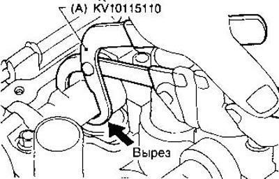
WARNING: Be careful not to damage the camshaft with the tool (A).
3. Rotate fixture (A), as shown in the figure to press the pusher down.
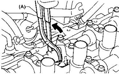
4. Install fixture (IN) between the pushrod and the camshaft to lock the pushrod in the pressed position.
WARNING: Attachment (IN) should be installed as close as possible to the bearing cap. Be careful not to damage the cam surface with the tool (IN).
5. Remove fixture (A).
6. Remove the shim using a small screwdriver and a magnetic grip.
7. Determine the required thickness of the new washer using the formula:
N = R + [M - 0.37 mm] for inlet valves or
N = R + [M - 0.40 mm] for exhaust valves,
where R is the thickness of the old washer, N is the thickness of the new washer, M is the measured valve clearance.
Use a micrometer to determine the thickness of the removed washer.
Spare parts are available in 50 sizes from 2.00 mm to 2.98 mm in 0.02 mm increments.
Select a new washer with a thickness closest to the calculated value.
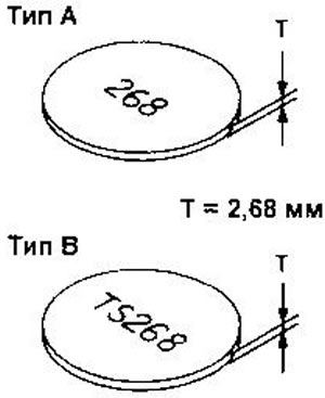
8. Install a new washer using a suitable tool. The surface with the embossed numbers should be facing down.
9. Install fixture (A), as described in points 2 and 3.
10. Remove fixture (IN).
11. Remove fixture (A).
12. Check clearance.
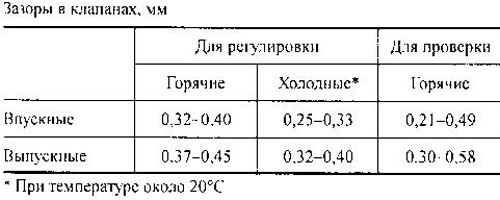
After adjusting the clearances on a cold engine, check their value on a warm engine and, if necessary, repeat the adjustment.